
 And I plan to use this charger board on the UPS board I am making.

1784 réponses à ce sujet
#21

Mike118
-
- Administrateur
-

- 12 509 messages
Staff Robot Maker
- Gender:Male
- Location:Anglet
- Interests:Robotique, Entrepreneuriat, Innovation, Programmation, Résolution de problème, Recherche de solutions, Mécanique, Electronique, Créer, Concevoir
Posté 14 janvier 2020 - 05:32
Yes it is a coil And I plan to use this charger board on the UPS board I am making.
And I plan to use this charger board on the UPS board I am making.
Si mon commentaire vous a plus laissez nous un avis ! 
Nouveau sur Robot Maker ?
Jetez un oeil aux blogs, aux tutoriels, aux ouvrages, au robotscope aux articles, à la boutique et aux différents services disponible !
En attendant qu'une bibliothèque de fichiers 3D soit mise en place n'hésitez pas à demander si vous avez besoin du fichier 3D d'un des produits de la boutique... On l'a peut être !
Si vous souhaitez un robot pilotable par internet n'hésitez pas à visiter www.vigibot.com et à lire le sous forum dédié à vigibot!
#22
Serveurperso
-

- Membres
-
- 3 428 messages
Pilier du forum
- Gender:Male
- Location:Paris
- Interests:Systèmes/Réseaux/Dev/Hardware/RF/Optique/Lasers...
Posté 04 février 2020 - 04:24
It's NOT a linear constant current source else 5V * 3A = 15 watts impossible to dissipate multiple watts on a small package. This is an efficient DC - DC Buck CC/CV charger with about 10/15% normal loss in heats.
I buyed 10 yesterday
I buyed 10 yesterday
Make your own raspberry robot, control it over the internet in FPV mode with super low latency and securely share access on it to your friends with Vigibot.com! You are welcome to test our robots now!
https://www.vigibot.com(100% free, no ads)
#23
Mike118
-
- Administrateur
-
- 12 509 messages
Staff Robot Maker
- Gender:Male
- Location:Anglet
- Interests:Robotique, Entrepreneuriat, Innovation, Programmation, Résolution de problème, Recherche de solutions, Mécanique, Electronique, Créer, Concevoir
Posté 13 mars 2020 - 10:39
UPS board design integrating all components is in progress. There were some room left so I added raws of servo like connectors GND VOLTAGE SIGNAL . Here was the early 3D concept of the board including the charger the step up the fuel gauge and capacitors ( all components are beetween the pi and the board to let space for the 1S2P battery in the middle ...)
Currently the voltage raws of the 2 group of pins were supposed to be directly connected to the battery voltage. And 5V and 3V pads were not supposed to be exposed on the board ... But I still have some space on the board. I can either choose to had two 2pins connectors GND 3.3V and GND 5V to expose them or use this space to make a " voltage selector "allowing you to choose what voltage you want on voltage raws on both of the group of pins ...
What is the best for you : two 2 pins connectors ? Or voltage selector ?


Currently the voltage raws of the 2 group of pins were supposed to be directly connected to the battery voltage. And 5V and 3V pads were not supposed to be exposed on the board ... But I still have some space on the board. I can either choose to had two 2pins connectors GND 3.3V and GND 5V to expose them or use this space to make a " voltage selector "allowing you to choose what voltage you want on voltage raws on both of the group of pins ...
What is the best for you : two 2 pins connectors ? Or voltage selector ?
Si mon commentaire vous a plus laissez nous un avis !
Nouveau sur Robot Maker ?
Jetez un oeil aux blogs, aux tutoriels, aux ouvrages, au robotscope aux articles, à la boutique et aux différents services disponible !
En attendant qu'une bibliothèque de fichiers 3D soit mise en place n'hésitez pas à demander si vous avez besoin du fichier 3D d'un des produits de la boutique... On l'a peut être !
Si vous souhaitez un robot pilotable par internet n'hésitez pas à visiter www.vigibot.com et à lire le sous forum dédié à vigibot!
#24
firened
-

- Membres
-
- 1 782 messages
Membre chevronné
- Gender:Male
Posté 13 mars 2020 - 12:22
i like the voltage selector.
there are more options for customization with a voltage selector, but both options work well because this is the ups board for minus. everything will already be setup and not many people will use custom stuff.
will 3.3V and 5V be accessible either way using the 40pin pi header?
there are more options for customization with a voltage selector, but both options work well because this is the ups board for minus. everything will already be setup and not many people will use custom stuff.
will 3.3V and 5V be accessible either way using the 40pin pi header?
#25
Mike118
-
- Administrateur
-
- 12 509 messages
Staff Robot Maker
- Gender:Male
- Location:Anglet
- Interests:Robotique, Entrepreneuriat, Innovation, Programmation, Résolution de problème, Recherche de solutions, Mécanique, Electronique, Créer, Concevoir
Posté 13 mars 2020 - 12:31
This is an UPS board that will be used on minus but I would like to use it on all my 1S vigibot robot  ( while the vigiboard hat can be used for any robot not only 1S.)
( while the vigiboard hat can be used for any robot not only 1S.)
Si mon commentaire vous a plus laissez nous un avis !
Nouveau sur Robot Maker ?
Jetez un oeil aux blogs, aux tutoriels, aux ouvrages, au robotscope aux articles, à la boutique et aux différents services disponible !
En attendant qu'une bibliothèque de fichiers 3D soit mise en place n'hésitez pas à demander si vous avez besoin du fichier 3D d'un des produits de la boutique... On l'a peut être !
Si vous souhaitez un robot pilotable par internet n'hésitez pas à visiter www.vigibot.com et à lire le sous forum dédié à vigibot!


#28
Mike118
-
- Administrateur
-
- 12 509 messages
Staff Robot Maker
- Gender:Male
- Location:Anglet
- Interests:Robotique, Entrepreneuriat, Innovation, Programmation, Résolution de problème, Recherche de solutions, Mécanique, Electronique, Créer, Concevoir
Posté 13 mars 2020 - 02:31
I will first send package to all Kickstarter backers then I will put the UPS on robot maker as a product you can buy 
Si mon commentaire vous a plus laissez nous un avis !
Nouveau sur Robot Maker ?
Jetez un oeil aux blogs, aux tutoriels, aux ouvrages, au robotscope aux articles, à la boutique et aux différents services disponible !
En attendant qu'une bibliothèque de fichiers 3D soit mise en place n'hésitez pas à demander si vous avez besoin du fichier 3D d'un des produits de la boutique... On l'a peut être !
Si vous souhaitez un robot pilotable par internet n'hésitez pas à visiter www.vigibot.com et à lire le sous forum dédié à vigibot!
#30
Mike118
-
- Administrateur
-
- 12 509 messages
Staff Robot Maker
- Gender:Male
- Location:Anglet
- Interests:Robotique, Entrepreneuriat, Innovation, Programmation, Résolution de problème, Recherche de solutions, Mécanique, Electronique, Créer, Concevoir
Posté 14 mars 2020 - 11:58
This is the current state of the design of the UPS board with the voltage selector. If you have suggestions it's time to make them

Si mon commentaire vous a plus laissez nous un avis !
Nouveau sur Robot Maker ?
Jetez un oeil aux blogs, aux tutoriels, aux ouvrages, au robotscope aux articles, à la boutique et aux différents services disponible !
En attendant qu'une bibliothèque de fichiers 3D soit mise en place n'hésitez pas à demander si vous avez besoin du fichier 3D d'un des produits de la boutique... On l'a peut être !
Si vous souhaitez un robot pilotable par internet n'hésitez pas à visiter www.vigibot.com et à lire le sous forum dédié à vigibot!
#31
firened
-
- Membres
-
- 1 782 messages
Membre chevronné
- Gender:Male
Posté 15 mars 2020 - 10:19
looks cool. i can see there wasn't much space available for all the things!
could it be useful if the charge IN+ IN- would have a second through hole in case someone wants to use a different charge port other than the usb C?
the last pin (gpio 28?) is not labeled.
GND is also not labeled in the vertical row, but there isn't space so I don't know.
could it be useful if the charge IN+ IN- would have a second through hole in case someone wants to use a different charge port other than the usb C?
the last pin (gpio 28?) is not labeled.
GND is also not labeled in the vertical row, but there isn't space so I don't know.

#33
Serveurperso
-
- Membres
-
- 3 428 messages
Pilier du forum
- Gender:Male
- Location:Paris
- Interests:Systèmes/Réseaux/Dev/Hardware/RF/Optique/Lasers...
Posté 15 mars 2020 - 12:58
www.vigibot.com -> Vigibot.com
c'est notre logo et son texte normalisé
c'est notre logo et son texte normalisé
Make your own raspberry robot, control it over the internet in FPV mode with super low latency and securely share access on it to your friends with Vigibot.com! You are welcome to test our robots now!
https://www.vigibot.com(100% free, no ads)
#34
Mike118
-
- Administrateur
-
- 12 509 messages
Staff Robot Maker
- Gender:Male
- Location:Anglet
- Interests:Robotique, Entrepreneuriat, Innovation, Programmation, Résolution de problème, Recherche de solutions, Mécanique, Electronique, Créer, Concevoir
Posté 15 mars 2020 - 02:42
There is no GPIO 28. (But the battery connector is a standard 3 pin connector like the one on ubec for RC models. with one room left. I think that this is what you though was the GPIO 28 ). And yes there is not a lot of space to label GND and Servo voltage... I am currently checking tiny details like pads form and size. I can choose to make all ground pads square for example ... Or I can choose to use a " white bottom overlay cover on the servo voltage pins " ... But Yes you get it this is the kind of suggestion I am seeking .
I was also thinking of using the free Pin on the batterry connector and connect it to Servo voltage ... This way with a little solder between this two pins and by cutting a trace it can be possible to have one group of servo connector connected to VBAT and one connected to 5V or 3.3V ...
About pads hole for charge ... The charger board will be directly put against the UPS board PCB. This means that we can't use a through hole pads on the rectangular space reserved for the charger ... But I can put a simple rectangular top pad. ( You can notice that there is non labeled rectangular pad on the botom near GPIO 18. This is the int pin from the Fuel Jauge. You can decide to connect it or not on the GPIO 18 with solder if you want ...)
@fire_ned and @Pascal is this better this way ? Should I label the fuel gauge int pad near GPIO 18 on the bottom ?
The GND label for the two groups of servo connectors will be hide by the hex stands ..
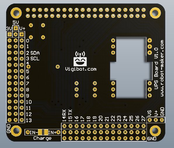
.I was also thinking of using the free Pin on the batterry connector and connect it to Servo voltage ... This way with a little solder between this two pins and by cutting a trace it can be possible to have one group of servo connector connected to VBAT and one connected to 5V or 3.3V ...
About pads hole for charge ... The charger board will be directly put against the UPS board PCB. This means that we can't use a through hole pads on the rectangular space reserved for the charger ... But I can put a simple rectangular top pad. ( You can notice that there is non labeled rectangular pad on the botom near GPIO 18. This is the int pin from the Fuel Jauge. You can decide to connect it or not on the GPIO 18 with solder if you want ...)
@fire_ned and @Pascal is this better this way ? Should I label the fuel gauge int pad near GPIO 18 on the bottom ?
The GND label for the two groups of servo connectors will be hide by the hex stands ..
Si mon commentaire vous a plus laissez nous un avis !
Nouveau sur Robot Maker ?
Jetez un oeil aux blogs, aux tutoriels, aux ouvrages, au robotscope aux articles, à la boutique et aux différents services disponible !
En attendant qu'une bibliothèque de fichiers 3D soit mise en place n'hésitez pas à demander si vous avez besoin du fichier 3D d'un des produits de la boutique... On l'a peut être !
Si vous souhaitez un robot pilotable par internet n'hésitez pas à visiter www.vigibot.com et à lire le sous forum dédié à vigibot!
#35
firened
-
- Membres
-
- 1 782 messages
Membre chevronné
- Gender:Male
Posté 15 mars 2020 - 03:29
ah yes. no gpio 28 
cool with the charge pads.
labeling the fuel gauge int pad sounds good to me.
oh i thought that's what you had in mind. to have the voltage selector only select the voltage for one row of servos. that the horizontal is routed to VBAT and the vertical row's voltage can be selected.
(i can take a look at the layer routing if you send the copper layers)
cool with the charge pads.
labeling the fuel gauge int pad sounds good to me.
oh i thought that's what you had in mind. to have the voltage selector only select the voltage for one row of servos. that the horizontal is routed to VBAT and the vertical row's voltage can be selected.
(i can take a look at the layer routing if you send the copper layers)
#36
Mike118
-
- Administrateur
-
- 12 509 messages
Staff Robot Maker
- Gender:Male
- Location:Anglet
- Interests:Robotique, Entrepreneuriat, Innovation, Programmation, Résolution de problème, Recherche de solutions, Mécanique, Electronique, Créer, Concevoir
Posté 15 mars 2020 - 03:34
Currently both raws are connected together. But they are not connected to any voltage by default. You have to manually connect them to something ( with the voltage selector or by soldering on the battery connector ) . You can also choose to use an external DC DC if you don't want to use the one on the board or VBAT...
VS can be connected to V+ ( = VBAT ) 5V or 3V ...
VS can be connected to V+ ( = VBAT ) 5V or 3V ...
Si mon commentaire vous a plus laissez nous un avis !
Nouveau sur Robot Maker ?
Jetez un oeil aux blogs, aux tutoriels, aux ouvrages, au robotscope aux articles, à la boutique et aux différents services disponible !
En attendant qu'une bibliothèque de fichiers 3D soit mise en place n'hésitez pas à demander si vous avez besoin du fichier 3D d'un des produits de la boutique... On l'a peut être !
Si vous souhaitez un robot pilotable par internet n'hésitez pas à visiter www.vigibot.com et à lire le sous forum dédié à vigibot!
#38
Mike118
-
- Administrateur
-
- 12 509 messages
Staff Robot Maker
- Gender:Male
- Location:Anglet
- Interests:Robotique, Entrepreneuriat, Innovation, Programmation, Résolution de problème, Recherche de solutions, Mécanique, Electronique, Créer, Concevoir
Posté 15 mars 2020 - 06:12
@fire_ned so what do you think about it ?


Si mon commentaire vous a plus laissez nous un avis !
Nouveau sur Robot Maker ?
Jetez un oeil aux blogs, aux tutoriels, aux ouvrages, au robotscope aux articles, à la boutique et aux différents services disponible !
En attendant qu'une bibliothèque de fichiers 3D soit mise en place n'hésitez pas à demander si vous avez besoin du fichier 3D d'un des produits de la boutique... On l'a peut être !
Si vous souhaitez un robot pilotable par internet n'hésitez pas à visiter www.vigibot.com et à lire le sous forum dédié à vigibot!
#39
firened
-
- Membres
-
- 1 782 messages
Membre chevronné
- Gender:Male
Posté 15 mars 2020 - 07:59
nice! i like it.
the charger board probably has an insulating silkscreen? so that it doesn't cause a short with the vias.
(oh, your vias will be covered too. neat)
if the 5V fill on the red layer, top left corner goes all the way to the edge of the board, it migh cause a short if the edge touches anything metal?
(it looks like there's some spacing but I can't tell)
do the hex stands and nuts fit onto the grey circles? else they scratch off the silkscreen.
the 3D rendering has 2 cutouts for the charger board, are they not necessary anymore?
argh i want one once they're available! hehe
the charger board probably has an insulating silkscreen? so that it doesn't cause a short with the vias.
(oh, your vias will be covered too. neat)
if the 5V fill on the red layer, top left corner goes all the way to the edge of the board, it migh cause a short if the edge touches anything metal?
(it looks like there's some spacing but I can't tell)
do the hex stands and nuts fit onto the grey circles? else they scratch off the silkscreen.
the 3D rendering has 2 cutouts for the charger board, are they not necessary anymore?
argh i want one once they're available! hehe
#40
Mike118
-
- Administrateur
-
- 12 509 messages
Staff Robot Maker
- Gender:Male
- Location:Anglet
- Interests:Robotique, Entrepreneuriat, Innovation, Programmation, Résolution de problème, Recherche de solutions, Mécanique, Electronique, Créer, Concevoir
Posté 15 mars 2020 - 08:41
@fire_ned
a) Both board have insulating silkscreen and vias are covered. So I am not concerned about this
 Yest there is a little spacing between the edge and any trace inculding the 5V fil on the red layer ( There is a " keep out layer " trace all around the board for this purpose, and also around the cut for the 5V step up )
c ) No the hex are a little bigger thant the grey circles ... So yes as I said before above, the hex will cover a little the two GND text lable, this is why I dont put the labels at the beginning ... I tested and nylon hex stands don't scratch off the silkscreen ... But I can also remove the two GND text label ... tell me what you think =)
d) Yes there are some change since the 3D rendering. No more cuts for the charger, the charger is soldered in the other direction. I still need to make the last 3D rendering with those modifications to double check if everything is ok. I already know that I will need to adjust a little the step up cut. But this is not a big deal at all. Just small ajustment that I know I have to do
e) I hope that it will be available for all kickstarter backers by the end of the month (as plannified ) / the beginning of next month ( with some delays ) . But due to the actual situation ( virus) it is very difficult to certify that all will go as planned ... So I appologize in advance for the possible delay ...
When all kickstarter packages will be shipped this boad will be available on www.robot-maker.com/shop
a) Both board have insulating silkscreen and vias are covered. So I am not concerned about this
Yest there is a little spacing between the edge and any trace inculding the 5V fil on the red layer ( There is a " keep out layer " trace all around the board for this purpose, and also around the cut for the 5V step up ) c ) No the hex are a little bigger thant the grey circles ... So yes as I said before above, the hex will cover a little the two GND text lable, this is why I dont put the labels at the beginning ... I tested and nylon hex stands don't scratch off the silkscreen ... But I can also remove the two GND text label ... tell me what you think =)
d) Yes there are some change since the 3D rendering. No more cuts for the charger, the charger is soldered in the other direction. I still need to make the last 3D rendering with those modifications to double check if everything is ok. I already know that I will need to adjust a little the step up cut. But this is not a big deal at all. Just small ajustment that I know I have to do
e) I hope that it will be available for all kickstarter backers by the end of the month (as plannified ) / the beginning of next month ( with some delays ) . But due to the actual situation ( virus) it is very difficult to certify that all will go as planned ... So I appologize in advance for the possible delay ...
When all kickstarter packages will be shipped this boad will be available on www.robot-maker.com/shop
Si mon commentaire vous a plus laissez nous un avis !
Nouveau sur Robot Maker ?
Jetez un oeil aux blogs, aux tutoriels, aux ouvrages, au robotscope aux articles, à la boutique et aux différents services disponible !
En attendant qu'une bibliothèque de fichiers 3D soit mise en place n'hésitez pas à demander si vous avez besoin du fichier 3D d'un des produits de la boutique... On l'a peut être !
Si vous souhaitez un robot pilotable par internet n'hésitez pas à visiter www.vigibot.com et à lire le sous forum dédié à vigibot!
Répondre à ce sujet


1 utilisateur(s) li(sen)t ce sujet
0 members, 1 guests, 0 anonymous users

