


Vigibot UPS HAT V1.0 documentation
By : Vigibot & Robot Maker

Product link : UPS Board Hat Kit V1.0
Content
1 : Material
2 : Introduction
3 : Soldering
4 : About the jumper and solder points J1 J2 et J3 .
5 : Mounting the UPS hat on the raspberry pi.
6 : Hacking the UPS to add a switch (optional)
1 : Material
- PCB UPS HAT * 1
- Chemical capacitor 2200µF * 1
- Ceramic capacitor 2.2µF * 1
- Header 2x20 for Raspberry pi * 1
- Header 40 pins black * 3
- Nylon screw M2.5 L6 * 4
- Nut M2.5 * 4
- Washer M2.5 * 4
- Spacer M2.5 male female L12 * 4
- Jumper * 1
- Step up * 1 ( red)
- Charger * 1 ( with USB C )
- I2C fuel gauge * 1
2 : Introduction
The UPS hat is a Raspberry pi hat used to
=> Provide a 5V 3A power supply to your raspberry pi from a 1S lithium battery (not compatible with 2S batteries or more ...)
=> Charge your battery without cutting the power to your raspberry pi (continue to use your robot even when it is charging!)
=> Indicate the charge level of your battery
=> Easily connect different external elements (such as sensors, servomotors, power supplies, etc.) to the GPIOs of a Raspberry Pi.
The UPS Hat is positioned directly on the Raspberry pi and is delivered in a kit to weld yourself with breakable strips to cut. Knowing how to solder and having the equipment to do it is therefore required required to assemble the elements of the kit (breakable strips, capacitors) on the card.
Like the vigiboard hat, there are two power supply rails for servo sockets. They are independent by default.
You can plug in the power source you want. However, be careful not to connect two different sources on the same rail ...
A socket is dedicated to the battery, and some options are "configurable: J1 J2 J3 and the position of the Jumper".
Warning :
The pins identified 3V and 5V are respectively directly connected to the 3.3V and 5V pins of the Raspberry pi. It is therefore advisable to take the necessary precautions concerning the current consumed and the possible disturbances brought by the connected elements.
You can connect low-power sensors to it, but avoid, for example, connecting several servomotors to the 5V of the Raspberry pi…
Note:
Some GPIOs are specific to functions, if you use these, the GPIOs concerned are no longer available for another use.
The I2C uses GPIO 2 (SDA) and GPIO 3 (SCL). You cannot use GPIO 2 and 3 for other things when using I2C.
UART uses GPIO 14 (TX) and GPIO 15 (RX). You cannot use GPIO 14 and 15 for anything else when using UART.
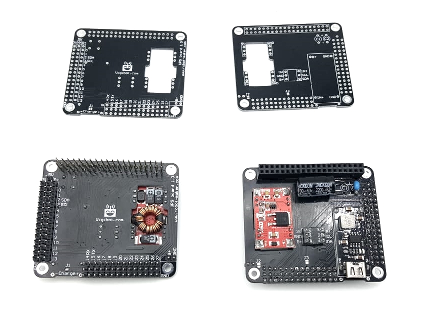
3 : Soldering
We have provided enough black breakawable header (3 of each) to cut so that you can solder all of the hat connectors.
Cutting proposal for assembly :
Header 1 : 16 + 15 + 3 + 3 + 3
Header 2 : 15 + 14 + 3 + 3 + 3 + 2
Header 3 : 14 + 14 + 4 (8 left)
Tips for soldering components:
1) Cut your breakable header to the right dimensions using a fine cutting pliers or break the bar using two flat pliers.
2) Solder the breakable headers, (be careful to put them on the right side of the PCB) check twice the picture below
3) Solder the charger the battery gauge and the step up (be careful on the side where you put them ... they go on the oposite side of the headers, follow the written indications on the pcb )
4) Solder the 2 * 20 connector.
5) Finally solder the capacitors.
Warning, the chemical capacitor is a polarized component, it is important to solder it in the correct direction. The tab - is indicated on the capacitor and on the PCB.
Note: When you solder the header first weld the two pins of the ends and check that the bar is perfectly in place before soldering all the other pins. This will make it easier to correct a possible positioning defect.
UPS hat conventionally welded with only black header, top and bottom with and without components:
4 : About the jumper and solder points J1 J2 and J3
By default the two supply rails of the two groups of connectors for servomotors are connected to nothing.
A voltage selector makes it possible to connect rail 1 to the supply voltage B+ (battery) or to the 5V or 3.3V of the Raspberry pi thanks to the jumper.
J1 allows to connect together rails 1 and 2 by making a weld point.
J2 is used to connect the power rails 2 directly to B+ (battery.)
J3 connects the battery gauge to pin 19 of the raspberry pi may be used for future development.
Warning: Never connect two different supply voltages together ...
Otherwise you can irreparably damage your Raspberry pi.
So avoid connecting V1 to V + and 5V at the same time!
Also avoid connecting V2 to V + and 3.3V at the same time!
By default we recommend welding J1 and not welding J2 and J3, this is what we do on the kits delivered welded.
Summary:
J1 soldered, J2 not soldered => The two rails are connected together, you can use the jumper to set the power supply on the two rails.
J1 & J2 both welded => the two rails are connected together at B + => Do not use the jumper in this case.
J1 not welded and J2 welded => The two rails are separated, ail 2 is connected to B+ but you can use the jumper to set the voltage on rail 1.
J3 not welded => reserved for automatic safe cut-off function of the raspberry pi in the event of too low level battery, new feature available soon.
Make your choice: Solder the solder points you want to use and set up your jumper in the position you want.
5 : Mounting the UPS Hat on the raspberry pi :
Warning : This step should be done with the batterie not connected to the UPS.
If you have not already done so, insert the ribbon cable of the raspberry pi camera into the csi camera slot on the raspberry pi. (The camera does not need to be mounted on the other end for the moment) You have to do it now because you will no longer be able to insert the camera ribbon cable without disassembly when you have mounted the UPS on the raspberry pi. So double check, that the ribbon cable is securely in its connector and that it is in the right direction.
Then you will need to use the following M2.5 Nylon hardware:
washers, 12mm male female hex spacers, 6mm length screws and nuts: 4 of each.
Note : If you have a minus chassis kit you can save a little time and start assembling the chassis to do so use 5mm male to female hex spacers to replace the 6mm length screws and 25mm male to female hex spacers which replace the nuts.
The assembly order is as follows:
6mm screw (or 5mm spacer) => Raspberry pi => washer => 12mm spacer => UPS hat => Nuts (or 25mm spacers)
Photo :
You can now connect your battery and if it is sufficiently charged your raspberry pi should boot and the robot will quickly connect to vigiot.
If your battery is not sufficiently charged, your robot will unfortunately fail to boot.
In this case it will be necessary to charge the battery alone on a charger.
If you don't have a charger you will need to separate the UPS from the raspberry pi long enough to let the battery charge.
If you let your robot exhaust all of its battery and turns off you will have to do this to make it boot again.
So avoid letting your robot exhaust all of its battery, it's not good for your SD card, and you will have to make this operation to turn it back on ...
6 : Hacking the UPS to add a switch (optional):
The robot being planned for a H24 use, it was not planned to put a switch to it, but that having been requested by the users we propose the following hack allowing to add a switch to turn off the robot while allowing the charge of the latter, thus facilitating the "resurrection of a robot" which would have run out of battery.
For those who wish, it is therefore necessary to execute the following operation (seen with and without the components)
In yellow a a trace is cut.
In pink two wires leading to a switch.
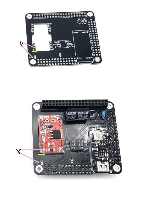
Warning, in this case choose a switch capable of supporting 3A.
We are thinking about the next version of the UPS integrating a way to put this switch more easily.


