Bonjour Dakota,
Hé oui c'est pas simple les IMU...
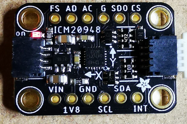
Il faudrait que tu précises avec quel IMU tu as fais tes tests.
A la lecture de tes commentaires, je suppose que tu n'utilises pas le DMP, ou alors que tu n'utilises pas les quaternions.
les quaternions sont des objets mathématiques indispensables dans les calculs d'angle des IMUs car ils evitent le drift et le gimball lock (je ne sais plus comment ça se dit)
Sans DMP, une calibration manuelle est nécessaire, ainsi que la fusion des données car aucun des instruments seul n'est assez fiable pour avoir une information pertinente.
C'est pour cela qu'il est vivement conseillé d'utiliser le DMP. il y a une autocalibration, mais ce n'est pas instantané : l'autocalibration s'apprend avec les mouvements reçus. Egalement le DMP fait la fusion des données et génére les quaternions pour les calculs.
Bon... De mon côté pour pouvoir t'aider j'ai refais mon banc de test avec l'affichage 3D de l'IMU et en utilisant la dernière librairie de Sparkfun pour le 20948.
Là je n'ai pas des bonnes nouvelles : le résultat est incohérent, et l'IMU chauffe comme pas possible, ce qui n'était pas le cas avec la version 'Alan'
Comme il y a pas mal de nouveautés sur ce banc de tests, je dois décortiquer un par un les points pour savoir d'ou vient le problème.
Ci-dessous le code source que j'ai utilisé, qui est celui de sparkfun modifié.
L'important c'est le début de la boucle loop, tu as le détail du calcul des 3 angles à partir des quaternions.
#include <Arduino.h>
#include "ICM_20948.h" // Click here to get the library: http://librarymanager/All#SparkFun_ICM_20948_IMU

ICM_20948_SPI icm20948;

#define CS_PIN PA4
#define SPI_FREQ 100000

#define SLAVE_SDA PB9
#define SLAVE_SCL PB8
#define SLAVE_ADR 0x21

TwoWire slaveI2C(SLAVE_SDA, SLAVE_SCL);

void receiveEvent(int);
void requestEvent();

void setup()
{
  // put your setup code here, to run once:

  Serial.begin(115200);
  Serial.println("Reseting");

  SPI.begin();

  slaveI2C.begin(SLAVE_ADR);
  // slaveI2C.setClock(SPI_FREQ);
  slaveI2C.onReceive(receiveEvent);
  slaveI2C.onRequest(requestEvent);

  bool initialized = false;
  while (!initialized)
  {

    icm20948.begin(CS_PIN, SPI, SPI_FREQ); // Here we are using the user-defined SPI_FREQ as the clock speed of the SPI bus

    Serial.print(F("Initialization of the sensor returned: "));
    Serial.println(icm20948.statusString());
    if (icm20948.status != ICM_20948_Stat_Ok)
    {
      Serial.println("Trying again...");
      delay(500);
      initialized = true;
    }
    else
    {
      initialized = true;
    }
  }

  // In this advanced example we'll cover how to do a more fine-grained setup of your sensor
  Serial.println("Device connected!");

  // Here we are doing a SW reset to make sure the device starts in a known state
  icm20948.swReset();
  if (icm20948.status != ICM_20948_Stat_Ok)
  {
    Serial.print(F("Software Reset returned: "));
    Serial.println(icm20948.statusString());
  }
  delay(250);

  // Now wake the sensor up
  icm20948.sleep(false);
  icm20948.lowPower(false);

  bool success = true; // Use success to show if the DMP configuration was successful

  // Initialize the DMP. initializeDMP is a weak function. In this example we overwrite it to change the sample rate (see below)
  success &= (icm20948.initializeDMP() == ICM_20948_Stat_Ok);

  // DMP sensor options are defined in ICM_20948_DMP.h
  //    INV_ICM20948_SENSOR_ACCELEROMETER               (16-bit accel)
  //    INV_ICM20948_SENSOR_GYROSCOPE                   (16-bit gyro + 32-bit calibrated gyro)
  //    INV_ICM20948_SENSOR_RAW_ACCELEROMETER           (16-bit accel)
  //    INV_ICM20948_SENSOR_RAW_GYROSCOPE               (16-bit gyro + 32-bit calibrated gyro)
  //    INV_ICM20948_SENSOR_MAGNETIC_FIELD_UNCALIBRATED (16-bit compass)
  //    INV_ICM20948_SENSOR_GYROSCOPE_UNCALIBRATED      (16-bit gyro)
  //    INV_ICM20948_SENSOR_STEP_DETECTOR               (Pedometer Step Detector)
  //    INV_ICM20948_SENSOR_STEP_COUNTER                (Pedometer Step Detector)
  //    INV_ICM20948_SENSOR_GAME_ROTATION_VECTOR        (32-bit 6-axis quaternion)
  //    INV_ICM20948_SENSOR_ROTATION_VECTOR             (32-bit 9-axis quaternion + heading accuracy)
  //    INV_ICM20948_SENSOR_GEOMAGNETIC_ROTATION_VECTOR (32-bit Geomag RV + heading accuracy)
  //    INV_ICM20948_SENSOR_GEOMAGNETIC_FIELD           (32-bit calibrated compass)
  //    INV_ICM20948_SENSOR_GRAVITY                     (32-bit 6-axis quaternion)
  //    INV_ICM20948_SENSOR_LINEAR_ACCELERATION         (16-bit accel + 32-bit 6-axis quaternion)
  //    INV_ICM20948_SENSOR_ORIENTATION                 (32-bit 9-axis quaternion + heading accuracy)

  // Enable the DMP Game Rotation Vector sensor (Quat6)
  success &= (icm20948.enableDMPSensor(INV_ICM20948_SENSOR_GAME_ROTATION_VECTOR) == ICM_20948_Stat_Ok);

  // Enable additional sensors / features
  // success &= (icm20948.enableDMPSensor(INV_ICM20948_SENSOR_RAW_GYROSCOPE) == ICM_20948_Stat_Ok);
  //success &= (icm20948.enableDMPSensor(INV_ICM20948_SENSOR_RAW_ACCELEROMETER) == ICM_20948_Stat_Ok);
  // success &= (icm20948.enableDMPSensor(INV_ICM20948_SENSOR_MAGNETIC_FIELD_UNCALIBRATED) == ICM_20948_Stat_Ok);

  // Configuring DMP to output data at multiple ODRs:
  // DMP is capable of outputting multiple sensor data at different rates to FIFO.
  // Setting value can be calculated as follows:
  // Value = (DMP running rate / ODR ) - 1
  // E.g. For a 225Hz ODR rate when DMP is running at 225Hz, value = (225/225) - 1 = 0.
  success &= (icm20948.setDMPODRrate(DMP_ODR_Reg_Quat6, 0) == ICM_20948_Stat_Ok); // Set to 225Hz
  //success &= (icm20948.setDMPODRrate(DMP_ODR_Reg_Accel, 0) == ICM_20948_Stat_Ok); // Set to 225Hz
  // success &= (icm20948.setDMPODRrate(DMP_ODR_Reg_Gyro, 0) == ICM_20948_Stat_Ok); // Set to 225Hz
  // success &= (icm20948.setDMPODRrate(DMP_ODR_Reg_Cpass, 0) == ICM_20948_Stat_Ok); // Set to 225Hz

  // Enable the FIFO
  success &= (icm20948.enableFIFO() == ICM_20948_Stat_Ok);

  // Enable the DMP
  success &= (icm20948.enableDMP() == ICM_20948_Stat_Ok);

  // Reset DMP
  success &= (icm20948.resetDMP() == ICM_20948_Stat_Ok);

  // Reset FIFO
  success &= (icm20948.resetFIFO() == ICM_20948_Stat_Ok);

  // Check success
  if (success)
  {
    Serial.println(F("DMP enabled!"));
  }
  else
  {
    Serial.println(F("Enable DMP failed!"));
    while (1)
      ; // Do nothing more
  }
}

double roll=0, pitch=0, yaw=0;
uint16_t droll=0,dpitch=0,dyaw=0 ;


void loop()
{
  // put your main code here, to run repeatedly:
  icm_20948_DMP_data_t data;
  icm20948.readDMPdataFromFIFO(&data);
  if ((icm20948.status == ICM_20948_Stat_Ok) || (icm20948.status == ICM_20948_Stat_FIFOMoreDataAvail)) // Was valid data available?
  {
    if ((data.header & DMP_header_bitmap_Quat6) > 0) // Check for GRV data (Quat6)
    {
      double q1 = ((double)data.Quat6.Data.Q1) / 1073741824.0; // Convert to double. Divide by 2^30
      double q2 = ((double)data.Quat6.Data.Q2) / 1073741824.0; // Convert to double. Divide by 2^30
      double q3 = ((double)data.Quat6.Data.Q3) / 1073741824.0; // Convert to double. Divide by 2^30

      double q0 = sqrt(1.0 - ((q1 * q1) + (q2 * q2) + (q3 * q3)));

      double q2sqr = q2 * q2;

      // roll (x-axis rotation)
      double t0 = +2.0 * (q0 * q1 + q2 * q3);
      double t1 = +1.0 - 2.0 * (q1 * q1 + q2sqr);
      double roll = atan2(t0, t1) * 180.0 / PI;

      // pitch (y-axis rotation)
      double t2 = +2.0 * (q0 * q2 - q3 * q1);
      t2 = t2 > 1.0 ? 1.0 : t2;
      t2 = t2 < -1.0 ? -1.0 : t2;
      double pitch = asin(t2) * 180.0 / PI;

      // yaw (z-axis rotation)
      double t3 = +2.0 * (q0 * q3 + q1 * q2);
      double t4 = +1.0 - 2.0 * (q2sqr + q3 * q3);
      double yaw = atan2(t3, t4) * 180.0 / PI;

      droll=roll ;
      dpitch=pitch ;
      dyaw=yaw ;

    }

    if ((data.header & DMP_header_bitmap_Accel) > 0) // Check for Accel
    {
      float acc_x = (float)data.Raw_Accel.Data.X; // Extract the raw accelerometer data
      float acc_y = (float)data.Raw_Accel.Data.Y;
      float acc_z = (float)data.Raw_Accel.Data.Z;
    }
  }
  if (icm20948.status != ICM_20948_Stat_FIFOMoreDataAvail) // If more data is available then we should read it right away - and not delay
  {
    delay(10);
  }
}

uint16_t command = 0;

void receiveEvent(int howMany)
{
  if (slaveI2C.available() < 1)
    return;
  uint8_t c = slaveI2C.read();
  if (c < 2)
    command = c;
  else
    command = 0;
}

void requestEvent()
{
  switch (command)
  {
  case 0:
    slaveI2C.write(0);
    break;
  case 1:
  {
    slaveI2C.write((uint8_t*)&dyaw,2) ;
    slaveI2C.write((uint8_t*)&dpitch,2) ;
    slaveI2C.write((uint8_t*)&droll,2) ;
  }
  }

}

// initializeDMP is a weak function. Let's overwrite it so we can increase the sample rate
ICM_20948_Status_e ICM_20948::initializeDMP(void)
{
  // The ICM-20948 is awake and ready but hasn't been configured. Let's step through the configuration
  // sequence from InvenSense's _confidential_ Application Note "Programming Sequence for DMP Hardware Functions".

  ICM_20948_Status_e result = ICM_20948_Stat_Ok; // Use result and worstResult to show if the configuration was successful
  ICM_20948_Status_e worstResult = ICM_20948_Stat_Ok;

  // Normally, when the DMP is not enabled, startupMagnetometer (called by startupDefault, which is called by begin) configures the AK09916 magnetometer
  // to run at 100Hz by setting the CNTL2 register (0x31) to 0x08. Then the ICM20948's I2C_SLV0 is configured to read
  // nine bytes from the mag every sample, starting from the STATUS1 register (0x10). ST1 includes the DRDY (Data Ready) bit.
  // Next are the six magnetometer readings (little endian). After a dummy byte, the STATUS2 register (0x18) contains the HOFL (Overflow) bit.
  //
  // But looking very closely at the InvenSense example code, we can see in inv_icm20948_resume_akm (in Icm20948AuxCompassAkm.c) that,
  // when the DMP is running, the magnetometer is set to Single Measurement (SM) mode and that ten bytes are read, starting from the reserved
  // RSV2 register (0x03). The datasheet does not define what registers 0x04 to 0x0C contain. There is definitely some secret sauce in here...
  // The magnetometer data appears to be big endian (not little endian like the HX/Y/Z registers) and starts at register 0x04.
  // We had to examine the I2C traffic between the master and the AK09916 on the AUX_DA and AUX_CL pins to discover this...
  //
  // So, we need to set up I2C_SLV0 to do the ten byte reading. The parameters passed to i2cControllerConfigurePeripheral are:
  // 0: use I2C_SLV0
  // MAG_AK09916_I2C_ADDR: the I2C address of the AK09916 magnetometer (0x0C unshifted)
  // AK09916_REG_RSV2: we start reading here (0x03). Secret sauce...
  // 10: we read 10 bytes each cycle
  // true: set the I2C_SLV0_RNW ReadNotWrite bit so we read the 10 bytes (not write them)
  // true: set the I2C_SLV0_CTRL I2C_SLV0_EN bit to enable reading from the peripheral at the sample rate
  // false: clear the I2C_SLV0_CTRL I2C_SLV0_REG_DIS (we want to write the register value)
  // true: set the I2C_SLV0_CTRL I2C_SLV0_GRP bit to show the register pairing starts at byte 1+2 (copied from inv_icm20948_resume_akm)
  // true: set the I2C_SLV0_CTRL I2C_SLV0_BYTE_SW to byte-swap the data from the mag (copied from inv_icm20948_resume_akm)
  result = i2cControllerConfigurePeripheral(0, MAG_AK09916_I2C_ADDR, AK09916_REG_RSV2, 10, true, true, false, true, true);
  if (result > worstResult)
    worstResult = result;
  //
  // We also need to set up I2C_SLV1 to do the Single Measurement triggering:
  // 1: use I2C_SLV1
  // MAG_AK09916_I2C_ADDR: the I2C address of the AK09916 magnetometer (0x0C unshifted)
  // AK09916_REG_CNTL2: we start writing here (0x31)
  // 1: not sure why, but the write does not happen if this is set to zero
  // false: clear the I2C_SLV0_RNW ReadNotWrite bit so we write the dataOut byte
  // true: set the I2C_SLV0_CTRL I2C_SLV0_EN bit. Not sure why, but the write does not happen if this is clear
  // false: clear the I2C_SLV0_CTRL I2C_SLV0_REG_DIS (we want to write the register value)
  // false: clear the I2C_SLV0_CTRL I2C_SLV0_GRP bit
  // false: clear the I2C_SLV0_CTRL I2C_SLV0_BYTE_SW bit
  // AK09916_mode_single: tell I2C_SLV1 to write the Single Measurement command each sample
  result = i2cControllerConfigurePeripheral(1, MAG_AK09916_I2C_ADDR, AK09916_REG_CNTL2, 1, false, true, false, false, false, AK09916_mode_single);
  if (result > worstResult)
    worstResult = result;

  // Set the I2C Master ODR configuration
  // It is not clear why we need to do this... But it appears to be essential! From the datasheet:
  // "I2C_MST_ODR_CONFIG[3:0]: ODR configuration for external sensor when gyroscope and accelerometer are disabled.
  //  ODR is computed as follows: 1.1 kHz/(2^((odr_config[3:0])) )
  //  When gyroscope is enabled, all sensors (including I2C_MASTER) use the gyroscope ODR.
  //  If gyroscope is disabled, then all sensors (including I2C_MASTER) use the accelerometer ODR."
  // Since both gyro and accel are running, setting this register should have no effect. But it does. Maybe because the Gyro and Accel are placed in Low Power Mode (cycled)?
  // You can see by monitoring the Aux I2C pins that the next three lines reduce the bus traffic (magnetometer reads) from 1125Hz to the chosen rate: 68.75Hz in this case.
  result = setBank(3);
  if (result > worstResult)
    worstResult = result;      // Select Bank 3
  uint8_t mstODRconfig = 0x04; // Set the ODR configuration to 1100/2^4 = 68.75Hz
  result = write(AGB3_REG_I2C_MST_ODR_CONFIG, &mstODRconfig, 1);
  if (result > worstResult)
    worstResult = result; // Write one byte to the I2C_MST_ODR_CONFIG register

  // Configure clock source through PWR_MGMT_1
  // ICM_20948_Clock_Auto selects the best available clock source – PLL if ready, else use the Internal oscillator
  result = setClockSource(ICM_20948_Clock_Auto);
  if (result > worstResult)
    worstResult = result; // This is shorthand: success will be set to false if setClockSource fails

  // Enable accel and gyro sensors through PWR_MGMT_2
  // Enable Accelerometer (all axes) and Gyroscope (all axes) by writing zero to PWR_MGMT_2
  result = setBank(0);
  if (result > worstResult)
    worstResult = result;  // Select Bank 0
  uint8_t pwrMgmt2 = 0x40; // Set the reserved bit 6 (pressure sensor disable?)
  result = write(AGB0_REG_PWR_MGMT_2, &pwrMgmt2, 1);
  if (result > worstResult)
    worstResult = result; // Write one byte to the PWR_MGMT_2 register

  // Place _only_ I2C_Master in Low Power Mode (cycled) via LP_CONFIG
  // The InvenSense Nucleo example initially puts the accel and gyro into low power mode too, but then later updates LP_CONFIG so only the I2C_Master is in Low Power Mode
  result = setSampleMode(ICM_20948_Internal_Mst, ICM_20948_Sample_Mode_Cycled);
  if (result > worstResult)
    worstResult = result;

  // Disable the FIFO
  result = enableFIFO(false);
  if (result > worstResult)
    worstResult = result;

  // Disable the DMP
  result = enableDMP(false);
  if (result > worstResult)
    worstResult = result;

  // Set Gyro FSR (Full scale range) to 2000dps through GYRO_CONFIG_1
  // Set Accel FSR (Full scale range) to 4g through ACCEL_CONFIG
  ICM_20948_fss_t myFSS; // This uses a "Full Scale Settings" structure that can contain values for all configurable sensors
  myFSS.a = gpm4;        // (ICM_20948_ACCEL_CONFIG_FS_SEL_e)
                         // gpm2
                         // gpm4
                         // gpm8
                         // gpm16
  myFSS.g = dps2000;     // (ICM_20948_GYRO_CONFIG_1_FS_SEL_e)
                         // dps250
                         // dps500
                         // dps1000
                         // dps2000
  result = setFullScale((ICM_20948_Internal_Acc | ICM_20948_Internal_Gyr), myFSS);
  if (result > worstResult)
    worstResult = result;

  // The InvenSense Nucleo code also enables the gyro DLPF (but leaves GYRO_DLPFCFG set to zero = 196.6Hz (3dB))
  // We found this by going through the SPI data generated by ZaneL's Teensy-ICM-20948 library byte by byte...
  // The gyro DLPF is enabled by default (GYRO_CONFIG_1 = 0x01) so the following line should have no effect, but we'll include it anyway
  result = enableDLPF(ICM_20948_Internal_Gyr, true);
  if (result > worstResult)
    worstResult = result;

  // Enable interrupt for FIFO overflow from FIFOs through INT_ENABLE_2
  // If we see this interrupt, we'll need to reset the FIFO
  // result = intEnableOverflowFIFO( 0x1F ); if (result > worstResult) worstResult = result; // Enable the interrupt on all FIFOs

  // Turn off what goes into the FIFO through FIFO_EN_1, FIFO_EN_2
  // Stop the peripheral data from being written to the FIFO by writing zero to FIFO_EN_1
  result = setBank(0);
  if (result > worstResult)
    worstResult = result; // Select Bank 0
  uint8_t zero = 0;
  result = write(AGB0_REG_FIFO_EN_1, &zero, 1);
  if (result > worstResult)
    worstResult = result;
  // Stop the accelerometer, gyro and temperature data from being written to the FIFO by writing zero to FIFO_EN_2
  result = write(AGB0_REG_FIFO_EN_2, &zero, 1);
  if (result > worstResult)
    worstResult = result;

  // Turn off data ready interrupt through INT_ENABLE_1
  result = intEnableRawDataReady(false);
  if (result > worstResult)
    worstResult = result;

  // Reset FIFO through FIFO_RST
  result = resetFIFO();
  if (result > worstResult)
    worstResult = result;

  // Set gyro sample rate divider with GYRO_SMPLRT_DIV
  // Set accel sample rate divider with ACCEL_SMPLRT_DIV_2
  ICM_20948_smplrt_t mySmplrt;
  // mySmplrt.g = 19; // ODR is computed as follows: 1.1 kHz/(1+GYRO_SMPLRT_DIV[7:0]). 19 = 55Hz. InvenSense Nucleo example uses 19 (0x13).
  // mySmplrt.a = 19; // ODR is computed as follows: 1.125 kHz/(1+ACCEL_SMPLRT_DIV[11:0]). 19 = 56.25Hz. InvenSense Nucleo example uses 19 (0x13).
  mySmplrt.g = 4; // 225Hz
  mySmplrt.a = 4; // 225Hz
  // mySmplrt.g = 8; // 112Hz
  // mySmplrt.a = 8; // 112Hz
  result = setSampleRate((ICM_20948_Internal_Acc | ICM_20948_Internal_Gyr), mySmplrt);
  if (result > worstResult)
    worstResult = result;

  // Setup DMP start address through PRGM_STRT_ADDRH/PRGM_STRT_ADDRL
  result = setDMPstartAddress();
  if (result > worstResult)
    worstResult = result; // Defaults to DMP_START_ADDRESS

  // Now load the DMP firmware
  result = loadDMPFirmware();
  if (result > worstResult)
    worstResult = result;

  // Write the 2 byte Firmware Start Value to ICM PRGM_STRT_ADDRH/PRGM_STRT_ADDRL
  result = setDMPstartAddress();
  if (result > worstResult)
    worstResult = result; // Defaults to DMP_START_ADDRESS

  // Set the Hardware Fix Disable register to 0x48
  result = setBank(0);
  if (result > worstResult)
    worstResult = result; // Select Bank 0
  uint8_t fix = 0x48;
  result = write(AGB0_REG_HW_FIX_DISABLE, &fix, 1);
  if (result > worstResult)
    worstResult = result;

  // Set the Single FIFO Priority Select register to 0xE4
  result = setBank(0);
  if (result > worstResult)
    worstResult = result; // Select Bank 0
  uint8_t fifoPrio = 0xE4;
  result = write(AGB0_REG_SINGLE_FIFO_PRIORITY_SEL, &fifoPrio, 1);
  if (result > worstResult)
    worstResult = result;

  // Configure Accel scaling to DMP
  // The DMP scales accel raw data internally to align 1g as 2^25
  // In order to align internal accel raw data 2^25 = 1g write 0x04000000 when FSR is 4g
  const unsigned char accScale[4] = {0x04, 0x00, 0x00, 0x00};
  result = writeDMPmems(ACC_SCALE, 4, &accScale[0]);
  if (result > worstResult)
    worstResult = result; // Write accScale to ACC_SCALE DMP register
  // In order to output hardware unit data as configured FSR write 0x00040000 when FSR is 4g
  const unsigned char accScale2[4] = {0x00, 0x04, 0x00, 0x00};
  result = writeDMPmems(ACC_SCALE2, 4, &accScale2[0]);
  if (result > worstResult)
    worstResult = result; // Write accScale2 to ACC_SCALE2 DMP register

  // Configure Compass mount matrix and scale to DMP
  // The mount matrix write to DMP register is used to align the compass axes with accel/gyro.
  // This mechanism is also used to convert hardware unit to uT. The value is expressed as 1uT = 2^30.
  // Each compass axis will be converted as below:
  // X = raw_x * CPASS_MTX_00 + raw_y * CPASS_MTX_01 + raw_z * CPASS_MTX_02
  // Y = raw_x * CPASS_MTX_10 + raw_y * CPASS_MTX_11 + raw_z * CPASS_MTX_12
  // Z = raw_x * CPASS_MTX_20 + raw_y * CPASS_MTX_21 + raw_z * CPASS_MTX_22
  // The AK09916 produces a 16-bit signed output in the range +/-32752 corresponding to +/-4912uT. 1uT = 6.66 ADU.
  // 2^30 / 6.66666 = 161061273 = 0x9999999
  const unsigned char mountMultiplierZero[4] = {0x00, 0x00, 0x00, 0x00};
  const unsigned char mountMultiplierPlus[4] = {0x09, 0x99, 0x99, 0x99};  // Value taken from InvenSense Nucleo example
  const unsigned char mountMultiplierMinus[4] = {0xF6, 0x66, 0x66, 0x67}; // Value taken from InvenSense Nucleo example
  result = writeDMPmems(CPASS_MTX_00, 4, &mountMultiplierPlus[0]);
  if (result > worstResult)
    worstResult = result;
  result = writeDMPmems(CPASS_MTX_01, 4, &mountMultiplierZero[0]);
  if (result > worstResult)
    worstResult = result;
  result = writeDMPmems(CPASS_MTX_02, 4, &mountMultiplierZero[0]);
  if (result > worstResult)
    worstResult = result;
  result = writeDMPmems(CPASS_MTX_10, 4, &mountMultiplierZero[0]);
  if (result > worstResult)
    worstResult = result;
  result = writeDMPmems(CPASS_MTX_11, 4, &mountMultiplierMinus[0]);
  if (result > worstResult)
    worstResult = result;
  result = writeDMPmems(CPASS_MTX_12, 4, &mountMultiplierZero[0]);
  if (result > worstResult)
    worstResult = result;
  result = writeDMPmems(CPASS_MTX_20, 4, &mountMultiplierZero[0]);
  if (result > worstResult)
    worstResult = result;
  result = writeDMPmems(CPASS_MTX_21, 4, &mountMultiplierZero[0]);
  if (result > worstResult)
    worstResult = result;
  result = writeDMPmems(CPASS_MTX_22, 4, &mountMultiplierMinus[0]);
  if (result > worstResult)
    worstResult = result;

  // Configure the B2S Mounting Matrix
  const unsigned char b2sMountMultiplierZero[4] = {0x00, 0x00, 0x00, 0x00};
  const unsigned char b2sMountMultiplierPlus[4] = {0x40, 0x00, 0x00, 0x00}; // Value taken from InvenSense Nucleo example
  result = writeDMPmems(B2S_MTX_00, 4, &b2sMountMultiplierPlus[0]);
  if (result > worstResult)
    worstResult = result;
  result = writeDMPmems(B2S_MTX_01, 4, &b2sMountMultiplierZero[0]);
  if (result > worstResult)
    worstResult = result;
  result = writeDMPmems(B2S_MTX_02, 4, &b2sMountMultiplierZero[0]);
  if (result > worstResult)
    worstResult = result;
  result = writeDMPmems(B2S_MTX_10, 4, &b2sMountMultiplierZero[0]);
  if (result > worstResult)
    worstResult = result;
  result = writeDMPmems(B2S_MTX_11, 4, &b2sMountMultiplierPlus[0]);
  if (result > worstResult)
    worstResult = result;
  result = writeDMPmems(B2S_MTX_12, 4, &b2sMountMultiplierZero[0]);
  if (result > worstResult)
    worstResult = result;
  result = writeDMPmems(B2S_MTX_20, 4, &b2sMountMultiplierZero[0]);
  if (result > worstResult)
    worstResult = result;
  result = writeDMPmems(B2S_MTX_21, 4, &b2sMountMultiplierZero[0]);
  if (result > worstResult)
    worstResult = result;
  result = writeDMPmems(B2S_MTX_22, 4, &b2sMountMultiplierPlus[0]);
  if (result > worstResult)
    worstResult = result;

  // Configure the DMP Gyro Scaling Factor
  // @param[in] gyro_div Value written to GYRO_SMPLRT_DIV register, where
  //            0=1125Hz sample rate, 1=562.5Hz sample rate, ... 4=225Hz sample rate, ...
  //            10=102.2727Hz sample rate, ... etc.
  // @param[in] gyro_level 0=250 dps, 1=500 dps, 2=1000 dps, 3=2000 dps
  result = setGyroSF(4, 3);
  if (result > worstResult)
    worstResult = result; // 4 = 225Hz (see above), 3 = 2000dps (see above)

  // Configure the Gyro full scale
  // 2000dps : 2^28
  // 1000dps : 2^27
  //  500dps : 2^26
  //  250dps : 2^25
  const unsigned char gyroFullScale[4] = {0x10, 0x00, 0x00, 0x00}; // 2000dps : 2^28
  result = writeDMPmems(GYRO_FULLSCALE, 4, &gyroFullScale[0]);
  if (result > worstResult)
    worstResult = result;

  // Configure the Accel Only Gain: 15252014 (225Hz) 30504029 (112Hz) 61117001 (56Hz)
  // const unsigned char accelOnlyGain[4] = {0x03, 0xA4, 0x92, 0x49}; // 56Hz
  const unsigned char accelOnlyGain[4] = {0x00, 0xE8, 0xBA, 0x2E}; // 225Hz
  // const unsigned char accelOnlyGain[4] = {0x01, 0xD1, 0x74, 0x5D}; // 112Hz
  result = writeDMPmems(ACCEL_ONLY_GAIN, 4, &accelOnlyGain[0]);
  if (result > worstResult)
    worstResult = result;

  // Configure the Accel Alpha Var: 1026019965 (225Hz) 977872018 (112Hz) 882002213 (56Hz)
  // const unsigned char accelAlphaVar[4] = {0x34, 0x92, 0x49, 0x25}; // 56Hz
  const unsigned char accelAlphaVar[4] = {0x3D, 0x27, 0xD2, 0x7D}; // 225Hz
  // const unsigned char accelAlphaVar[4] = {0x3A, 0x49, 0x24, 0x92}; // 112Hz
  result = writeDMPmems(ACCEL_ALPHA_VAR, 4, &accelAlphaVar[0]);
  if (result > worstResult)
    worstResult = result;

  // Configure the Accel A Var: 47721859 (225Hz) 95869806 (112Hz) 191739611 (56Hz)
  // const unsigned char accelAVar[4] = {0x0B, 0x6D, 0xB6, 0xDB}; // 56Hz
  const unsigned char accelAVar[4] = {0x02, 0xD8, 0x2D, 0x83}; // 225Hz
  // const unsigned char accelAVar[4] = {0x05, 0xB6, 0xDB, 0x6E}; // 112Hz
  result = writeDMPmems(ACCEL_A_VAR, 4, &accelAVar[0]);
  if (result > worstResult)
    worstResult = result;

  // Configure the Accel Cal Rate
  const unsigned char accelCalRate[4] = {0x00, 0x00}; // Value taken from InvenSense Nucleo example
  result = writeDMPmems(ACCEL_CAL_RATE, 2, &accelCalRate[0]);
  if (result > worstResult)
    worstResult = result;

  // Configure the Compass Time Buffer. The I2C Master ODR Configuration (see above) sets the magnetometer read rate to 68.75Hz.
  // Let's set the Compass Time Buffer to 69 (Hz).
  const unsigned char compassRate[2] = {0x00, 0x45}; // 69Hz
  result = writeDMPmems(CPASS_TIME_BUFFER, 2, &compassRate[0]);
  if (result > worstResult)
    worstResult = result;

  // Enable DMP interrupt
  // This would be the most efficient way of getting the DMP data, instead of polling the FIFO
  // result = intEnableDMP(true); if (result > worstResult) worstResult = result;

  return worstResult;
}