


Vigiboard hat kit
Made by : Vigibot & Robot Maker

Contents List
1 : Kit Contents
2 : Presentation of the Vigiboard hat
3 : Weld elements on the Vigiboard hat
4 : Note as regards the use of jumpers with V1 and V2
1: Kit Contents
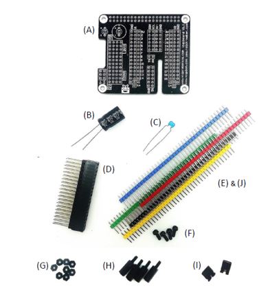
- PCB vigiboard * 1
- Chemical Capacitor 2200µF * 1
- Ceramic Capacitor 2.2µF * 1
- Connector 2x20 for Raspberry pi * 1
- Pin header strip 40 pins black * 4
- Nylon Screws M2.5 L6 * 4
- Nut M2.5 * 8
- Spacer M2.5 male female L12 * 4
- Jumper * 2
- Bonus :
Pin header strip 40 pins yellow * 4
Pin header strip 40 pins red * 2
Pin header strip 40 pins green * 2
Pin header strip 40 pins blue * 2
Pin header strip pins white * 2
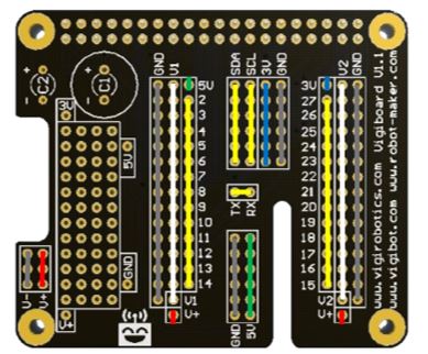
2: Presentation of the Vigiboard
The Vigiboard hat is a Raspberry pi hat allowing easy connection of outside elements (like sensors, servomotors, alimentations…) to GPIO of Raspberry Pi. It is directly placed on the Raspberry pi and delivered as a kit to weld by yourself with pin header strip. Knowing how to solder and having the material is therefore required to assemble elements of the kit (pin header strip, capacitor) to the carte.
Power rails V1 and V2 are independents plugs for servomotors by default. You can plug in the power source that you wish.
Nevertheless, pay attention to not plug two different powers sources on the same rails…
Warning:
Pins identify by 3V et 5V have respectively a direct connection to the pins 3.3V and 5V of the Raspberry pi. It’s suitable to take care according to the currant consumed and potential perturbations brought by connected elements. It’s possible to connect sensor low consumer of current but we avoid, for example, to connect many servomotors on the 5V of Raspberry pi…
Note :
Some GPIO are specify to a specific functions, if you use it, the concerned GPIO could be not available to a different use.
The I2C use by GPIO 2 (SDA) and the GPIO 3 (SCL).
Therefore, you can’t use GPIO 2 and 3 for another thing if you are using the I2C.
The UART use the GPIO 14 (TX) and the GPIO 15 (RX).
You can ’t use GPIO 14 and 15 for another thing if you are using the UART.
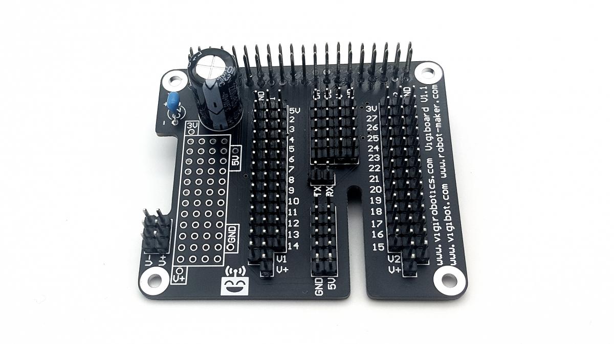
3: Weld elements on the Vigiboard hat
We have provided enough black and yellow divisible pin header strip (4 of each) to allow you to solder all connectors of the hat in these of two colors. However, because of we also provided pin header strip with other colors in bonus, you can choose to weld your connector with different colors to highlight function or customize the carte according to your preferences.
Cutting proposition for assembly with pin header strip of the same color:
Barrette 1 : 14 + 14 + 6 + 6
Barrette 2 : 16 + 16 + 6 + 2
Barrette 3 : 15 + 3 + 3 + 6 (rest 13)
Barrette 4 : 15 + 6 + 6 (rest 13)
Cutting proposition for assembly with pin header strip of different colors:
Back => GND
Barrettes of 15 * 2, 6 * 2 and 3 * 1.
Red => V+
Barrettes of 3 * 1 and a single pin * 2.
White => V1 and V2
Barrettes of 14 * 2.
Blue => 3V
Barrettes of 6 * 1 and a single pin * 1
Green=> 5V
Barrettes of 6 * 1 et a single pin * 1
Yellow => GPIO, SDA, SCL, RX TX
Barrettes of 13 * 2, 6 * 2 and 2 * 1
Advise to weld components:
Cut you pin header strip in right dimensions thanks to a thin bolt cutter or break the barrette with two pliers, to make it accuracy on the right place.
First, weld pin header strip, then connector 2*20. Weld capacitors in last. Warning, the chemical capacitor is a polarize component, it’s important to weld it in the right sense. The capacitor paste - is indicated on the capacitor and on the PCB.
When you weld barrettes, weld first the ends and check your barrette is perfectly placed before to weld all the other pins. In this way, it could be easier to correct a potential positioning default.
Vigiboard hat weld in classical way with only blacks pins headers strip:
4: Note as regard the use of jumpers with V1 and V2
By default, power rails V1 and V2 of the two groups of connectors for servomotors are linked to nothing. It’s possible to connect them easily to the supply voltage V+ or to the 5V or else to 3.3V of the Raspberry pi thanks to a jumper.
Warning: Never connect two different supply tension together…
Otherwise you risk to damage irreparably your Raspberry pi.
Therefore, avoid to link V1 to V+ and 5V in the same time !
In the same way, avoid to link V2 to V+ and 3.3V in the same time !
Simple PDF :
Printable PDF
buy link : https://www.robot-maker.com/shop/shield/410-vigiboard-hat-v11.html
Shipping all around the world.
If you have any question feel free to ask.


![[Guide] How to use DECTalk, the Moonbase Alpha Voice, on your robot - dernier message par firened](https://www.robot-maker.com/forum/uploads/profile/photo-thumb-16821.jpg?_r=1639321316)
![[Mars Attacks!] Participating in the French Robot Cup 2024 ( Eurobot 2024) - dernier message par TNERA](https://www.robot-maker.com/forum/uploads/profile/photo-thumb-17784.png?_r=1662890323)


