Aller au contenu


Photo

Rethinking the Quadruped project


  • Veuillez vous connecter pour répondre
20 réponses à ce sujet

#1 TNERA

TNERA

    Membre occasionnel

  • Membres
  • Pip
  • 135 messages

Posté 19 juin 2023 - 11:00

Hi all!


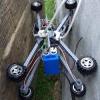
Inspired by the successful Quadruped builds at TRR, I'm eager to try another build. From the posts that have been made recently, I've learned about the importance of stronger servos, better batteries, and lighter weight. In my previous builds, I encountered issues with weak servos and excessive robot weight.

For my next project, I'm seeking advice on the servo/distribution/battery aspects. For an 8 or 12 DoF robot, I will need a lot of servos, and suitable battery. Hopefully, I could find the magical affordable servos with a torque of 40kg/cm and a speed of 0.1 s / 60°!

Regarding the electrical requirements, I need help calculating the required current flow and determining the appropriate battery capacity (C value). Should I assume that the stall current multiplied by the number of servos represents the maximum requirement? Or is there a larger requirement due to the combined impulse of all the servos?

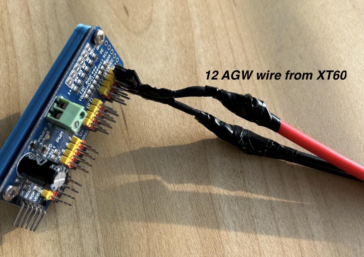
I'm also rethinking power distribution. Would a custom board be necessary, considering the possibility of expanding the design to a 12DoF configuration?  This is obviously beyond the capabilities of a PCA9685.


Thanks!


#2 Oracid

Oracid

    Pilier du forum

  • Modérateur
  • PipPipPipPipPip
  • 7 024 messages
  • Gender:Male

Posté 20 juin 2023 - 07:03

The battery Parick used for Felin is this one (TATTU LiPo Batterie 2300mAh 11.1V 45C 3S), https://www.amazon.f...1zcF9hdGY&psc=1


The most the C value is high, the most the battery can delivers high intensity instantly. Drone batteries seem to be the best fit.

I dont know if the PCA9685 will stand 8 or 12 servos with that intensity. That's one of my next test.

For information, I will start using a shield, not a PCA9685.


In my opinion, it will be very difficult to find a low cost servo with 40kg.cm torque and 0.10s/60° speed.


#3 Oracid

Oracid

    Pilier du forum

  • Modérateur
  • PipPipPipPipPip
  • 7 024 messages
  • Gender:Male

Posté 20 juin 2023 - 01:43

Here, for you. https://www.robot-ma...0kgcm/?p=118850


#4 pat92fr

pat92fr

    Membre passionné

  • Membres
  • PipPipPip
  • 762 messages
  • Gender:Male

Posté 20 juin 2023 - 07:31

I have used this battery for the TRR for 12V servo : https://www.amazon.f...product_details


The overall current should be less than about 3 x STALL_CURRENT with a 12 DOF quadruped, but the power supply must be able to support inrush/peak current (start up sequence, touch down torque..). Do not use switched BEC or DC/DC converter between battery and servo.


Good luck !


#5 TNERA

TNERA

    Membre occasionnel

  • Membres
  • Pip
  • 135 messages

Posté 22 juin 2023 - 10:41

Thanks both,

question, slightly off topic, does anyone have recommendations for the charging devices for these types of batteries? I know it needs to be LiPo, and there are different qualities of chargers out there, some with discharge capability and certainly with ability to view across the cells while charging. DroneBot Workshop had a great tutorial on this. but my question is ... any favorite devices here in Europe?


#6 pat92fr

pat92fr

    Membre passionné

  • Membres
  • PipPipPip
  • 762 messages
  • Gender:Male

Posté 22 juin 2023 - 10:45

This one ! I have got two devices, both charging two batteriy packs. 


#7 TNERA

TNERA

    Membre occasionnel

  • Membres
  • Pip
  • 135 messages

Posté 08 juillet 2023 - 10:16

Thanks for the recommendations.  The charger is quiet nice and now part of my workshop. 

The battery is much lighter than I expected, I see now how 'you all' are able to keep the weight of the quadrupeds down.


From an electrical perspective, using 11.1V for 12V servos makes sense. 

I will take your advice:
"Do not use switched BEC or DC/DC converter between battery and servo."


I need to upgrade my servos to 12V, next step.  and get a 7.4V for my mg995 servos.


thanks!


#8 Oracid

Oracid

    Pilier du forum

  • Modérateur
  • PipPipPipPipPip
  • 7 024 messages
  • Gender:Male

Posté 08 juillet 2023 - 01:09

I need to upgrade my servos to 12V, next step.  and get a 7.4V for my mg995 servos.

In my opinion, the MG995 servo is too heavy for a small quadruped and has not enough torque for a big quadruped.
For a small quadruped like I done till now, I suggest MG92B servo.
For a big quadruped like Patrick has done or which I am making in to day project, I suggest 40kg.cm torque servos.
 
 
A cheap 40kg.cm torque servo :


#9 TNERA

TNERA

    Membre occasionnel

  • Membres
  • Pip
  • 135 messages

Posté 21 mai 2024 - 01:27

Here is an update on my project. It got pushed aside last year, but is now back on track.
 
Here is my highly biased video of the little robot standing up. Biased because I don't show the failures. :D
 
 
In this video, I am "using what I have," which is the heavy, slow MG995 servos. They are powered at 5V with a battery bank with a max current of 3A. It is working but a little wobbly. It is slow, with a 300ms pause between steps.
 
Based on previous discussions, I now have a new LiPo battery with 2200mAh, 7.4V, and a 50C discharge rating. This voltage slightly exceeds the MG995 rating of 7.2V. What is your experience with over-powering these servos? Is there a high risk of burnout, or is it generally okay? Adding a voltage regulator would only limit the current capacity. Are there workarounds for this?
 
Concern 2: I am using small MG90 servos to provide additional degrees of freedom, bringing the total to 12. These have a lower voltage rating of just 6V max. I am thinking this circuit would also need to be separate.  
 
thanks!


#10 Oracid

Oracid

    Pilier du forum

  • Modérateur
  • PipPipPipPipPip
  • 7 024 messages
  • Gender:Male

Posté 21 mai 2024 - 08:20

I have used many times MG995 or MG996 and SG90 with 7.4V (2S) Lipo battery with no issue.

But, there is a but, I burned a lot of servos, without knowing the reason.

I think that when a servo is blocked, whatever the voltage, if the intensity increases, there is a moment where things end badly.


About the video, with short, it seems not possible to show it on the forum.


#11 TNERA

TNERA

    Membre occasionnel

  • Membres
  • Pip
  • 135 messages

Posté 25 mai 2024 - 09:06

I have used many times MG995 or MG996 and SG90 with 7.4V (2S) Lipo battery with no issue.


Thanks Oracid, that gives me the confidence that I will do no worse, than to burn them up!   :laugh1:

I will charge up and try it this weekend!  seriously, it is good to know that it is possible.  And I am guessing from previous conversation that putting any voltage reducer would be counter productive.

I find it interesting, as my last robot (the one that followed your 5bar design), really had the same issue.  I got it all the way up to the same point here, where the servos are just under powered.  This robot is much lighter and with in the capability of the servos.  I just need to add some more juice!


#12 Mike118

Mike118

    Staff Robot Maker

  • Administrateur
  • PipPipPipPipPip
  • 10 122 messages
  • Gender:Male
  • Location:Anglet
  • Interests:Robotique, Entrepreneuriat, Innovation, Programmation, Résolution de problème, Recherche de solutions, Mécanique, Electronique, Créer, Concevoir

Posté 25 mai 2024 - 03:11


About the video, with short, it seems not possible to show it on the forum.

Yes " short links " are not " supported" (yet ? ) but, we can get the correct link from youtube that is supported. I updated the message to have the video directly displayed on the forum.


Si mon commentaire vous a plus laissez nous un avis  !  :thank_you:

Nouveau sur Robot Maker ? 

Jetez un oeil aux blogs, aux tutoriels, aux ouvrages, au robotscope  aux articles,  à la boutique  et aux différents services disponible !
En attendant qu'une bibliothèque de fichiers 3D soit mise en place n'hésitez pas à demander si vous avez besoin du fichier 3D d'un des produits de la boutique... On l'a peut être ! 
Si vous souhaitez un robot pilotable par internet n'hésitez pas à visiter www.vigibot.com et à lire le sous forum dédié à vigibot!


Les réalisations de Mike118  


#13 TNERA

TNERA

    Membre occasionnel

  • Membres
  • Pip
  • 135 messages

Posté 01 juin 2024 - 09:34

Yes " short links " are not " supported" (yet ? ) but, we can get the correct link from youtube that is supported. I updated the message to have the video directly displayed on the forum.

Ok, I see what you did there. I will use that next time. (I did try multiple times to get it to work!)

thanks for fixing!!


#14 TNERA

TNERA

    Membre occasionnel

  • Membres
  • Pip
  • 135 messages

Posté 02 juin 2024 - 11:52

OK, so I did it - hooked up the 7.4 50C battery to my quadruped and It did not burn down on the first test!!   :Koshechka_08:


For this purpose, I have connected the battery directly to the power bus of the PCA9685. This provides the power to the servos directly bypassing a capacitor and regulator.
 
I found myself needing to connect 12 AWG wires from an XT-60 connector to the pins on a servo controller. I managed to make an unholy soldered connection between the large wires using an old servo socket/connector, which worked for my prototype, but I know this is not the correct method.
 
connector-pca9685.jpg
 
Question: How do you safely connect XT-60 battery connectors and their thick 12 AWG wires to small electronics? I have the XT-60 connectors (both male and female), but the challenge is connecting the large wires down from the battery connector to the smaller boards.
 
[updated note:  the Servo board will drive 8 MG995 servos as mention before, I am expecting ~20A current at peak.  well in the range for the 50c battery, its just that the connector needs to survive this to.]


#15 Oracid

Oracid

    Pilier du forum

  • Modérateur
  • PipPipPipPipPip
  • 7 024 messages
  • Gender:Male

Posté 02 juin 2024 - 05:19

Question: How do you safely connect XT-60 battery connectors and their thick 12 AWG wires to small electronics?


Connecteur mâle et femelle vers Futaba JST SM, adaptateur de charge, câble de convertisseur, fil pour batterie RC, 22AWG, 100mm, Count60 - AliExpress

Connecteur de batterie Xt60 Rc Lipo | Connecteurs de batterie Lipo Xt 60-Puissance en ligne Xt60-Aliexpress

Câble adaptateur de chargeur, longueur de ligne Ames, 10cm, tête DuPont AS150, compte 90, JST, mâle 600, adaptateur, prise, compte 60 à compte 30 - AliExpress

Câble adaptateur de charge de batterie pour salle de bain, 2 pièces Rotterdam khobby count60 femelle à count30 mâle/JST mâle/DuPont mâle 18AWG tête pour TA D6 TOl'hyKITRC M8 (aliexpress.com)


#16 Sandro

Sandro

    Membre chevronné

  • Modérateur
  • PipPipPipPip
  • 1 318 messages
  • Gender:Male

Posté 02 juin 2024 - 09:13

@Oracid : excepted if explicitly rated otherwise, I don't think most of the linked connectors can wistand 20A.

@TNERA : those male pins you are using are not suited at all for 20A. Most such pins are rated 3A or less. The highest I have ever seen is 7A.


If you don't mind soldering, and you have a cutter and a small drill, you can just use some bare copper PCB (ie all the PCB covered with a continous plane of copper). You just cut the PCB at the required size (with a cutter, a metal saw or a Dremel), then cut the plane in 2 (for + and -), and drill as many holes as required. If each "track" is 10mm wide, for 20A continous, the temperature rise should be <30°C. If you want to go a bit thinner, cover your "tracks" with a thick layer of solder. NB : make sure you use PCBs with only copper, no photo-sensible varnish on top (ie buy PCBs for CNC machining, not for chemical etching).

You can also use prototyping PCBs full of holes, with copper lines connecting the holes. I would recomment you use at least 3 lines for + and 3 for -, and that you cover them with a thick layer of solder (including connecting the 3 lines together).


You can also just solder all the wires together (ugly but space efficient).


There might also be some specialized connectors, but if the wire diameter is significantly different, it's often hard to find an adequate conenctor


Aidez-nous à vous aider : partagez toutes les informations pertinentes : description précise du problème, contexte, schéma de câblage, liens vers la documentation des composants, votre code (ou encore mieux un code minimal reproduisant le bug), ...

Vous recevrez ainsi plus de réponses, et elles seront plus pertinentes.


#17 Oracid

Oracid

    Pilier du forum

  • Modérateur
  • PipPipPipPipPip
  • 7 024 messages
  • Gender:Male

Posté 03 juin 2024 - 06:13

@Oracid : excepted if explicitly rated otherwise, I don't think most of the linked connectors can wistand 20A.


Don't you think that the weak point would be the PCA9685 board first, before the power wires.


#18 TNERA

TNERA

    Membre occasionnel

  • Membres
  • Pip
  • 135 messages

Posté 03 juin 2024 - 04:29

Thanks both, 


I see where you are going.  I can get a better XT-60 connector with a JR connector or like at the end.  But, it will still be the Pins and traces on the PCA9685 that will be 'next' to melt.  And that a potential fix is to potentially build a board with better connector and thicker traces to the individual pins.  That would make a better longer term solution!


thanks!


#19 Oracid

Oracid

    Pilier du forum

  • Modérateur
  • PipPipPipPipPip
  • 7 024 messages
  • Gender:Male

Posté 03 juin 2024 - 08:08

I understand your concern, to you and Sandro.
Out of ignorance, I do things that people who have skills would not do.
I just ask you to consider this quadruped which has very powerful servos, 56kg.cm.
And yet, I had no problem with a shield that you can see in the video, at 3'51 ".


#20 Sandro

Sandro

    Membre chevronné

  • Modérateur
  • PipPipPipPip
  • 1 318 messages
  • Gender:Male

Posté 03 juin 2024 - 08:56

we don't know the real total current consumend by all the servos together, and for how long. A 10µs peak of 20A is no problem even for very thin wire/tracks. What counts, is more the average over a few seconds.
If this average remains low enough, then everything should be OK.
The problem is that there is no way to garantee this with your robots as far as I know (you could add current measurements, and shut-down the motors in case of an overcurrent, or use an e-fuse). So probably, at normal use, it will work (wires/tracks might already get a bit hot). But in case of a "bad situation" (for example, you press the robot down by hand, and all motors go full force to resist your push), it's quite likely that the wires/tracks will get very hot, or even melt.

If you want to test the limit of wires/tracks without much calculation, there is one simple method that usually works (no garantee, you might still do some damage) : start with a small current, and keept it for 1 minute, with your fingers on the components (wire, connector, track, ...) you want to test. If you can keep your fingers on them, then you can increase a bit the current, and start again (ie keep touching for 1 minute). Repeat until it becomes too hot to keep your fingers on the wire/track/connector. Then go back to the previous setting : it should be a rather safe setting (wires and tracks are OK as long as they are cold enough for you to touche them ; for connectors, some might start to get soft a bit earlier)


Aidez-nous à vous aider : partagez toutes les informations pertinentes : description précise du problème, contexte, schéma de câblage, liens vers la documentation des composants, votre code (ou encore mieux un code minimal reproduisant le bug), ...

Vous recevrez ainsi plus de réponses, et elles seront plus pertinentes.


0 utilisateur(s) li(sen)t ce sujet

0 members, 0 guests, 0 anonymous users