Top Posters


Newest Members
-
 1. Pachup
Joined: avril 27 2026 12:57
-
 2. Gaspard
Joined: avril 13 2026 01:20
-
 3. RySen
Joined: mars 22 2026 10:09
-
 4. garfield2142
Joined: févr. 02 2026 09:15
-
 5. Lerochem
Joined: janv. 28 2026 12:34
Recently Added Posts
-
 Naissance de mon Sumo
pmdd - mai 11 2026 09:34
J'aime beaucoup le côté "Dalton" de tes 3 mini-sumos! :lol: Effet de perspe...
-
 Naissance de mon Sumo
Gédé - mai 11 2026 09:24
J'aime beaucoup le côté "Dalton" de tes 3 mini-sumos! :lol: Effet de perspe...
-
[Mars Attacks! ] Coupe de france de robotique 2026 !
pmdd - mai 11 2026 03:48
Superbe !
-
Naissance de mon Sumo
pmdd - mai 11 2026 02:10
Bonjour à tous, Préparation du tournoi de Nîmes ce WE, les 3 mini-sumos...
-
 Etude de conception d'une imprimante 3D XXXL
levend - mai 10 2026 09:49
Je n'avais pas parlé de longueur illimitée mais c'est une bonne idée... Pendant u...
Naissance de mon Sumo
Bonjour
Dans la rubrique "Naissance de...", après mon quadrupède, je vous présente mon nouveau projet, toujours avec un concours en vue : la construction d'un mini sumo.
Ce n'est pas un projet très original mais il me convient dans la progression de ma formation pico/python. Par rapport au quadrupède il y aura plus de code et plus de capteurs.
Le mini sumo est très compact (10x10) et le terrain est très petit (diamètre 77 cm) . Un des avantages c'est que j'arrêterai de courir après mon robot, comme je fais depuis 6 mois avec Jag'Bot I
Je pense faire trois sumos:
* Un "basique", le premier pour me faire la main
* Un "costaud", solide sur ses roues
* Un "agile" que j'imagine avec des roues mécanum
Je pense aussi concevoir un système de déploiement, à voir.
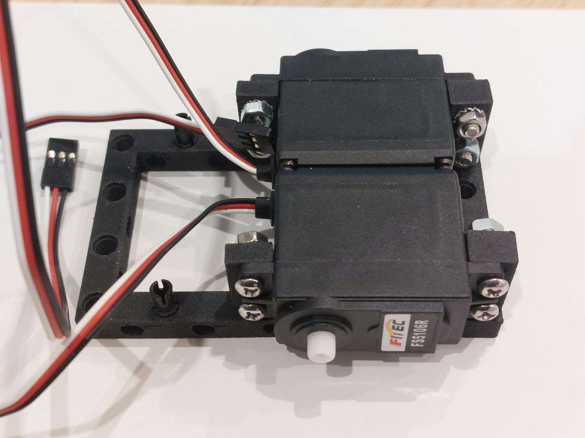
Je retiens toujours le même principe, la fixation des moteurs/servos et de la batterie est un support imprimé 3D mais avec des trous compatibles Lego (diamètres et espacements) , ce qui me permet de construire par modules et de progresser petit à petit, quitte à coller la version finale.
Voici le point de départ :


36â¯226 Views ·
247 Replies
( Last reply by pmdd )

[Mars Attacks! ] Coupe de france de robotique 2026 !
Pour ceux qui l'auraient raté, le règlement de la coupe de robotique 2026 est tombée début septembre en version "Béta" !
Petite présentation du thème de cette année " The winter is coming " et des différentes actions à faire réaliser par les robots avec " Barbatronic " qui de l'équipe "Les karibous", ( une des équipes soutenues par Robot Maker  ) et qui chaque année participe en présentant la préparation de ses robots au fur et à mesure :
Vous pouvez retrouver les documents en versions téléchargeable directement sur le site de planète science : https://www.coupederobotique.fr/edition-2026/reglement-2026/
Les inscriptions sont ouvertes donc n'hésitez pas !
Cette année encore je vais y participer avec l'équipe Mars Attacks! =).
1â¯513 Views ·
4 Replies
( Last reply by pmdd )
Etude de conception d'une imprimante 3D XXXL
En ce moment j'ai le temps de réfléchir ...
Aujourd'hui je regardait le prix des imprimantes 3D du style bambulab X1C (apparemment plus produite) ou la X2D (bien trop cher) avec l'AMS de préférence et la Creality K1 Max abordable (la K1 Max combo un peu moins abordable mais...), j'aurais vu ça il y a quelques mois j'en aurais acheté une.
Il y a quelques semaines j'ai vu une imprimante 3D, qui était sur le point de sortir, qui m'a fait plaisir parce qu'elle prouve que les idées que j'avais il y a quelques années n'étaient pas si farfelues que ça : un changement automatique de buses, comme un changement d'outils sur un centre d'usinage. J'avais une cette idée dans un projet de grosse imprimante 3D avec d'autres idées qui n'ont pas leur place sur nos petites machines surtout avec les AMS de Bambulab (et similaire chez la concurrence) mais pourquoi pas sur de plus grosses machines.
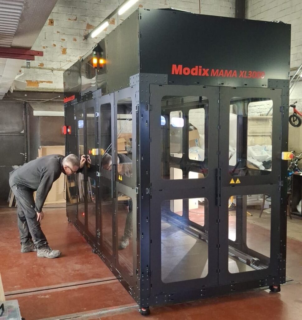
https://www.modix3d.com/mama-xl3000/
Aujourd'hui j'ai vu une imprimante 3D qui m'a fait rêver, une imprimante de grande taille, la Modix MAMA XL3000, avec :
- plateau fixe
- chambre chauffée (60°)
- alimentation filament 2.85
- Débit : 160 mm3/s jusqu'à 500g/h
- buse : jusqu'à 1,6mm
- option pellets à venir (Débit : 500mm3/s jusqu'à 3kg/h, buse jusqu'à 5mm)
- Volume d'impression : 1000 x 1000 x 3000 mm
J'aime bien les imprimantes XX...XL, je ne connais pas le prix de cette imprimante mais sa petite soeur avec un volume d'impression de "seulement" 1000 x 1000 x 1700 mm coûte 56000 € (oui c'est bien 56k€).
Comme vous le savez j'aime bien concevoir, et donc ici ce ne sera que de la conception, pas de réalisation sauf si quelqu'un est intéressé par la réalisation et qu'il a le budget. Cette imprimante serait tout à fait réalisable par une petite équipe de passionnés. Personnellement même s'il y a quelques années j'aurais été tenté mais actuellement ce n'est pas le cas j'ais assez de soucis comme ça, je me lance dans la conception parce que j'aime la conception et ça me fait du bien de pensez à autre chose.
Vous avez bien compris , c'est juste une étude, pas de réalisation (j'insiste sur ce point parce il y en a qui ne comprennent pas).
Pour rappel : la Modix MAMA XL3000 est composée avec des composants courants et des composants plus spécifique à la marque Modix.
Parmi les composants on retrouve la carte DUET 6HC, l'extrudeur Pellet de Dyze Design, , la structure est en profilés alu rainuré 80x80, les vis à billes sont peut-être de meilleure qualité que ce que l'on achèterait, tout comme les guidages.
Je pense qu'il est possible de construire une imprimante similaire pour un prix moindre, mais je suis joueur je veux lui donner des caractéristiques différentes en ajoutant des idées que j'avais il y a quelques années et des idées inspirées d'autres modèles d'imprimante 3D XXL (3DP EXCEL)
Vous m'aiderez en ajoutant des options que vous souhaiteriez
.
Voici un début de ce que je souhaiterais :
- Volume d'impression de (h x l x L) :1000 x 1000 x 3000 mm (soit 1 x 1 x 3 m), même si en réalité je souhaiterais plus grand pour imprimer une chose que j'aimerais bien voir imprimé en 3D, pour le fun
- Modulaire
- Plateau fixe
- Débit élevé
- Vitesse d'impression
- Chambre isolée et chauffée
- Multi-filaments (supports solubles)
- Changement de buses automatisé
- Chargement automatique des bobines de filaments depuis un magasin
- Stockage des filaments dans un environnement contrôlé
J'avais d'autres idées qui se sont envolées  .
.
Ne me taper pas dessus en disant qu'il ne faut pas faire de grande imprimante, c'est faisable avec du temps et de l'argent, il ne s'agit que d'un rêve qui fait un pas vers la réalité.
Je suis toujours aussi fou sur la dimensions de mes projets ...
60 Views ·
2 Replies
( Last reply by levend )
Applications
Latest Discussions
-
Etude de conception d'une imprimante 3D XXXL
levend - mai 09 2026 09:18
-
Multi-filaments et multi-buses
levend - mai 08 2026 01:52
-
Demande d'aide sur l'électronique d'un flipper
Pachup - avril 27 2026 04:23
-

-
 Formation : conception de PCBs pour résister aux décharges ESD
Sandro - févr. 23 2026 06:26
Statistiques de la communauté
- Total des messages
- 114â¯570
- Total des membres
- 5â¯020
- Dernier membre
- Pachup
- Record de connectés simultanés
- 22â¯661
26 avril 2026


