Aller au contenu


Photo

5Bar Quadruped - Mojo4


  • Veuillez vous connecter pour répondre
45 réponses à ce sujet

#1 TNERA

TNERA

    Membre occasionnel

  • Membres
  • Pip
  • 100 messages

Posté 06 novembre 2021 - 12:39

Hi All,


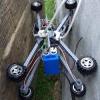
I am truly inspired by Oracid's development of quadrupeds. I am going to attempt to repeat his work using my own style. I would think of this as a 'peer review' process. Perhaps in trying to repeat the progress we all learn something new and innovative.


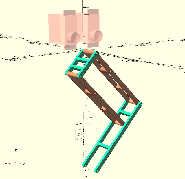
I think a lot of my design principles are similar to others in the forum. Simple solutions, using commonly available (affordable) parts. I like to use 3D printed parts. I design all my parts using OpenSCAD.


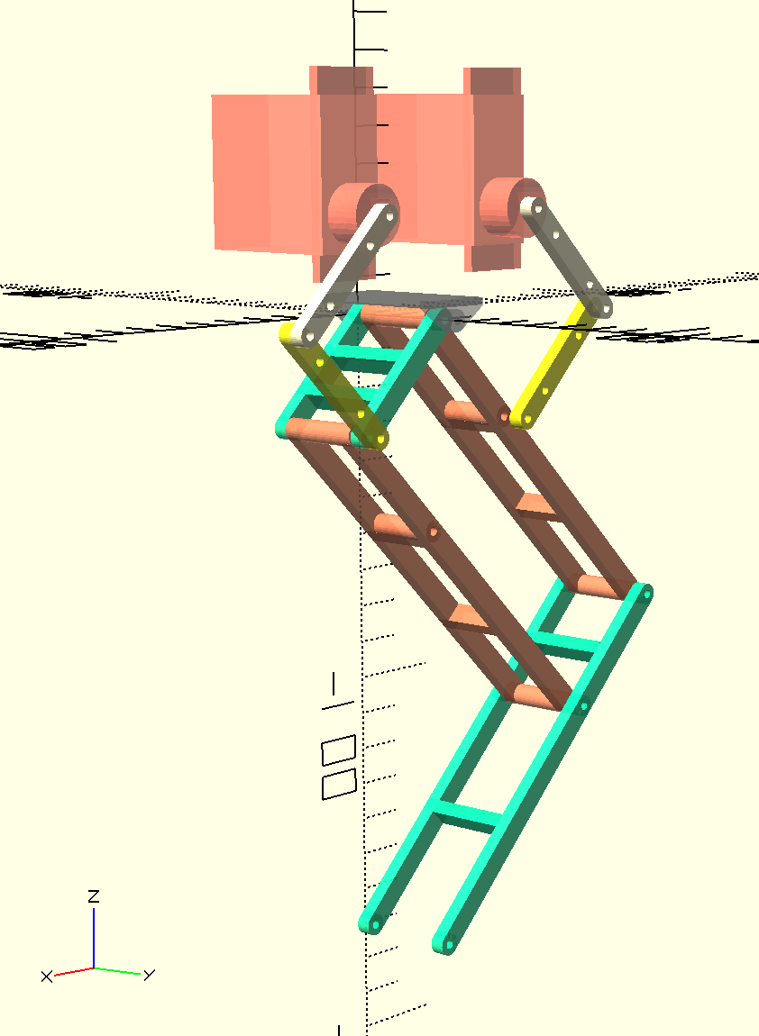
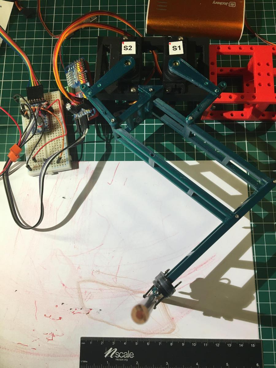
Mojo4 will be my 4th quadruped design. I have tried different styles of legs. the 5 bar looks to be very promising. I really like that the leg joint is supported directly at the chassis, and not completely at the servo.


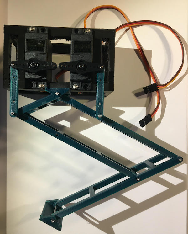
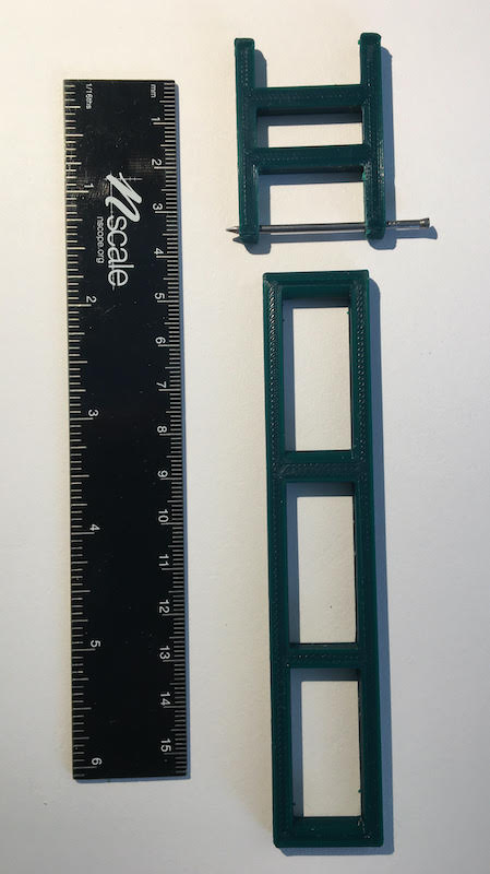
For this leg I am going attempt using a 'hinge' type joint. The hinge will be 3D print and the pin will be a small nail (clou). I believe this will be enough for the actuation, and provide rigid stability against wobble. We shall see.


5bar-parts.jpeg


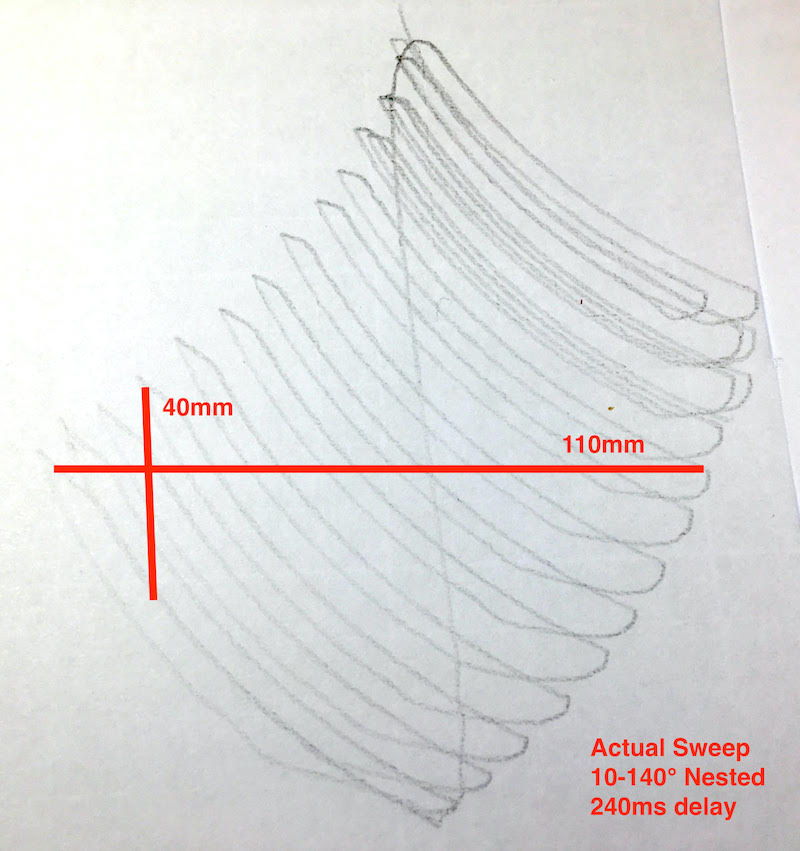
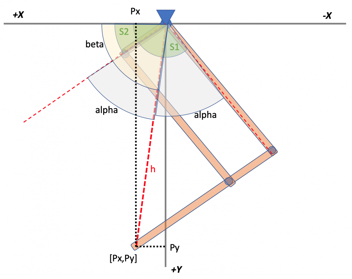
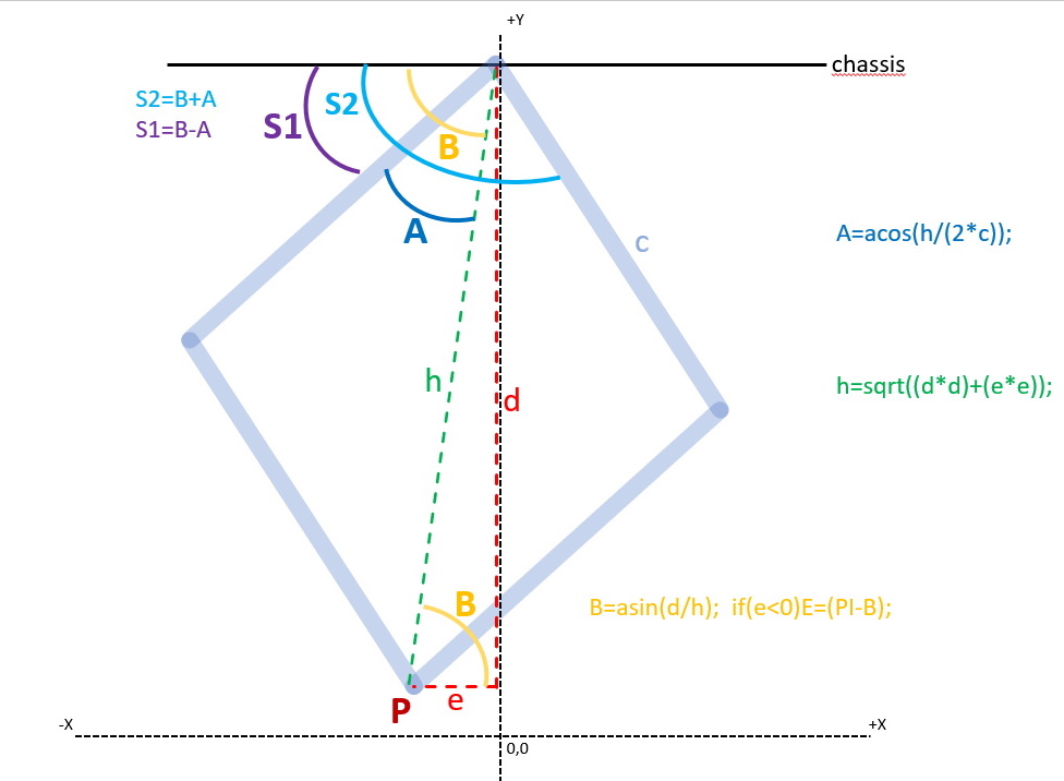
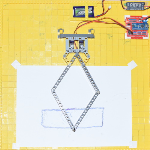
Right now I am focused on the basics of getting the leg to work with the 5Bar technique:


mojo4-5bar_design.png


Questions for the experts ... :)


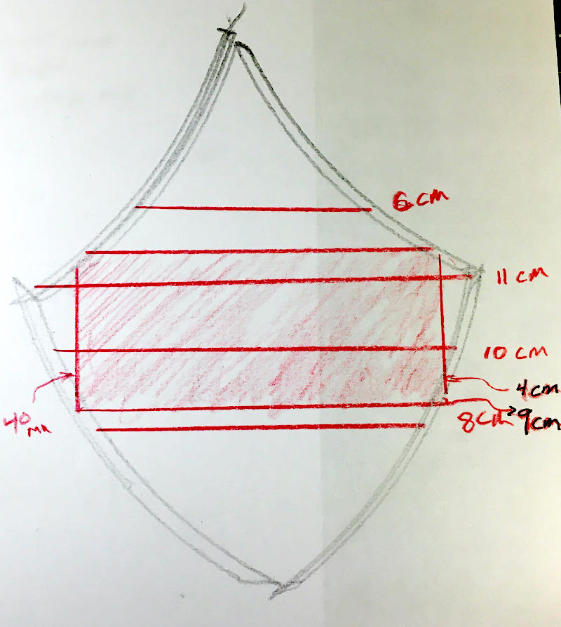
1) did you find any suggested/magic ratio for the separation between the 2 servos?

2) did you find any suggested/magic length ratio for the 'control arms' the lifters (l1) and (p1) ?? I am reading old posts to see what you all discussed. any helpful suggestions!

-- right now I am planning on L & P to be identical in length and form a 90 degree angle with the 5Bar ©


Thanks,

(TNERA) - Doug


  • Mike118 , Forthman et pat92fr aiment ceci

#2 Oracid

Oracid

    Pilier du forum

  • Modérateur
  • PipPipPipPipPip
  • 6 769 messages
  • Gender:Male

Posté 06 novembre 2021 - 03:00

Hi Doug. Very glad to see that !


Be careful that the rungs of the ladders do not restrict movements. At this scale, they are not necessarily needed in Lego. It is up to you.
Maybe screws rather than nails. There are nylon screws.
 
1) The good news is that you can put the both servos where you want. You only have to worry that it must be a parallelogram between the servo arm and the femur side of the the diamond(paw). Keep in mind that the real length of the servo arm is the lenght of the diamond side. In my Quad it is 112mm. The Lego unit is 8mm. That means 8mm between two holes center. In your case about 10cm. The same is for the both servos. Even if one looks shorter than the other. A paralellogram between  servo arm and diamond side simplify calculations.
 
2) To simplify calculations, it is better that the both femur and tibia have the same length. I am not sure to understand what you mean about the 90°. It could be any degree.
 
Don't hesitate to ask, you are welcome.
I am sure you will do it. 


#3 Oracid

Oracid

    Pilier du forum

  • Modérateur
  • PipPipPipPipPip
  • 6 769 messages
  • Gender:Male

Posté 07 novembre 2021 - 02:52

Hi Doug.


In this video, https://www.robot-maker.com/forum/topic/13445-5bqe-2-5-barres-quadrupede-avec-extension/?p=113549 , you can see details about the mounting.


Tell me !

Do you want to make a 8 DOF or a 12 DOF ?

Did you choose the servos ?


#4 TNERA

TNERA

    Membre occasionnel

  • Membres
  • Pip
  • 100 messages

Posté 07 novembre 2021 - 05:15

So far everything is coming along nicely.


Thanks for the magic-insight:

You only have to worry that it must be a parallelogram between the servo arm and the femur side of the the diamond(paw). Keep in mind that the real length of the servo arm is the length of the diamond side.


This is the advice I think i needed. my 'rapid-prototype' will not have this. but it is only to test out the approach and get a feel for the mechanics and code.  Now that you point it out, I can see that it is important to make the calculations easier.


here is the (updated) planned arrangement of servo-horn, servos, and lifters.

mojo4-5bar-legdesign.png


Here is my 'rapid prototype'.  I have the newly printed 5bar legs in dark green.  I am reusing parts from my old Mojo2 project. This includes the servos.  These are MG995 servos. I had planned on using these since they were successful in Mojo2, plus I had them available.  I only have 8 of them, so - hmmmn - 8 DoF for now. :)

mojo4-prototype-leg-Sun6Nov.jpeg


I will start with 8DoF just to get all of the basics of walking to work.  Then I will attempt to Level UP! (to catch up with you.  ha ha)


Next for me is to jump into the code. Thanks for posting in Git!  I will let you know how that goes.


  • Melmet et pat92fr aiment ceci

#5 Oracid

Oracid

    Pilier du forum

  • Modérateur
  • PipPipPipPipPip
  • 6 769 messages
  • Gender:Male

Posté 07 novembre 2021 - 06:35

Yes, the junction between the servo axis and the diamond side must be a parallelogram and better, a diamond.

The parallelogram is a 4 bars, but a particular 4 bars. Your 4 bars is not bad, but more complex to use.
Your shoes  is good but it could better if it stand with rubber band.
Your servos weigh are 65g each. It's far too heavy on this scale. I recommend MG92B, or at least MG90S.
MG92B is recommended for 6V, but I use 2S Lipo batterie, 7.4V for more torque and it is ok.
Unfortunately my supplier is out of stock. https://fr.aliexpres....685f6c37C02N2k
 
Here a video to show that a 4 bars could be complex.


#6 TNERA

TNERA

    Membre occasionnel

  • Membres
  • Pip
  • 100 messages

Posté 08 novembre 2021 - 10:33

Thanks Oracid,


yes, the shoe or Servo horns, in the pictures are temporary.  I want to get everything moving first, then I will replace with a custom horn/shoe that longer. I plan on having the horn be 40mm, to make the control arm into a true diamond.  As you mentioned above, it will be simpler.  And it seems that it would produce a slightly larger 'work area' for the paw. (correct me if I am wrong here).


About those servo initializations and calibrations.  This is what I see in the code and imagine on the robot...  (this might be hard to write)

- you initialize the LS & RS to 70° (respectfully given that R is backward -180)

- At this initialization point, I am guessing you connect-set the shoe/horn onto the servo output shaft so that the lifter/leg is positioned with the paw directly under then main diamond.   --This would be your initial position, and the correct placement of the servo horn on the servo output shaft.


From here, are you considering this the [0,0] position of [x,y]?

Then all of your gait arrays in the code represent absolute distance from [0,0] in mm?


Does my question make sense?


#7 Oracid

Oracid

    Pilier du forum

  • Modérateur
  • PipPipPipPipPip
  • 6 769 messages
  • Gender:Male

Posté 09 novembre 2021 - 08:54

Does my question make sense?

Of course, yes !


What is a "horn" ? If it is the servo arm, my servo arm is 3L (3 Lego unit). That make 3 x 8 = 24mm.

On my last Quads, the connector between the servo and the femur is a 24mm diamond sided. 


- Which , code/video are you refering ? As you want to make a 8 DOF Quad, I suggest to refer to 5BQE-2, https://www.robot-ma...avec-extension/

- In the video, https://www.robot-ma...nsion/?p=113549, at 1'56" you see how to mount the servo arms.

- Then at 2'45", I explain how to calibrate the servos. In this version, the 'a' variable (line 33) is 60°, not 70°, but this does not matter, it depends on the lenght of the gauge.

The top extremity of the gauge is on the main diamond axis. The bottom extremity of the gauge is on the extremity of the paw(or diamond). Keep in mind that the paw is a diamond.

- First you have to calibrate the left servo with modifyingt the error value, line 12. That make the extremity of the paw in the good X value.

- Then you have to calibrate the right servo with modifyingt the error value, line 12. That make the extremity of the paw in the good Y value.

- Yes, the [0,0] point is the origin X/Y. This is the bottom of the diagonal of the diamond. All the values of the tables are from this point and in millimeter.

- Beware, left and right legs are symmetrical.


I guess, mainly, you have understood the principle.
If you make your Quad exactly with the same sizes of 5BQE- 2 it will work the same.
 
Don't hesitate to ask.

  • TNERA aime ceci

#8 TNERA

TNERA

    Membre occasionnel

  • Membres
  • Pip
  • 100 messages

Posté 10 novembre 2021 - 11:22

I have wired my test leg up and starting to play with it.

I have started with some basic "Servo Sweeps" using the two (L & R) servos.  I am interested by the amount of 'working space' available to the leg. This is the maximum extent that the leg can get to with the combination of the two servos.  Naturally, any future 'gait' will have to fit inside this area.


I attached a pencil to the foot and manually move the servos through the usable range (avoiding the 'singularities').  this is the resulting theoretical usable space:

5bar-working-areat-trace.jpeg

I am seeing about 9cm in the x direction. for y, 4 easy to use, enough to lift the leg.  There are more space available, which might be good for 'striking a pose' :)


I programmed in a basic "Nested" sweep between 10° and 140° (servo angles only - i do not have Inverse Kinematics set up yet).  This is the resulting "Actual" pattern that should be available.  I was pleased that it is somewhat close to the theoretical space.

5bar-actual-area.jpeg


This was all very interesting to me. 

1- one of the first observations that I had is that a delay is needed in the gait or sweep to allow the servo time to arrive at the programmed point. This Time delay - you have it listed as speed , will have a dramatic effect on the size of this work area.  The faster the change, the more likily that the servo will not arrive in time to leave for the next programmed location.

2- next, give that the leg has a known working area. and that working area is defined by the 'speed' of the settings. Then it is entirely possible to calculate the maximum speed of the leg (and robot).  [10m in 10 seconds? eh??  :) ]


What experience do others have in getting similar results for the  Working Area of a 5 bar leg?


#9 Oracid

Oracid

    Pilier du forum

  • Modérateur
  • PipPipPipPipPip
  • 6 769 messages
  • Gender:Male

Posté 11 novembre 2021 - 08:36

What experience do others have in getting similar results for the  Working Area of a 5 bar leg?

I guess the way to experiment is to lay the leg horizontally on a table with a pen at the extremity as you did.
An other way is to attach the leg on a tower with a paper on back. This is a good way as you can put a load on the leg.
On YouTube, you can too look for Scara Robot.
About the speed, it is worse that you can imagine when you test on a real life walking. Of course the Speed variable is what you have to modify. But you have to test if it is better to delay after each servo move or after the 2 servos move.
This could be very confusing. We made a lot of test here, please have a look, https://www.robot-ma...rs-plus-rapide/
 
But as you know with your own experiments, the first goal is to make it walking.


#10 TNERA

TNERA

    Membre occasionnel

  • Membres
  • Pip
  • 100 messages

Posté 13 novembre 2021 - 11:06

Wow, thanks, that thread was quite a dialog about gait and speed.  Very nice.


Did you have a similar thread on Inverse Kinematics?  :)


I am currently working through this step. (pun?) I have read a paper on the dynamics and a good set of maths to support it.  Also, I have a modified version of your code on the 8DoF and 12Dof as well as some others.  On your code, I have a few questions:


  float d=Ay-Py, e=Ax-Px;                     //
  float h=sqrt((d*d)+(e*e));                  //
  float E=acos(d/h);    if(e<0)E=(-E);        //
  float G=acos(h/(2*c));                      // Diamond half top A angles
  float GL=(PI/2)-G-E;                        // left servo angle
  float GR=(PI/2)-G+E;                        // right servo angle


- Is the value Ay (=180) used to adjust the 'origin' 0,0 position for the cartisian coordinates?  If not, how do you do that?
- Just curious, what words are the calculation step values supposed to be (h, d, e, E, G)??  knowing what names they represent might help my understanding
- the variable c (=112) must represent the length of a leg segment. since they are all the same length in the diamond shape, it simplifies things, perhaps. I kind of expected it to be in some other parts of the equation.
- the use of 'acos' surprised me.  I was expecting 'atan2', since atan2 solves the quadrant identification issue.  So I am really curious how you developed
the math with acos instead of atan2.
-  What does this do?  "if (! digitalRead(0)) resetFunc();"??  does this help some of the stability issues between calls?
 
I am sure there is a lot of other magic I am missing!!
 
[my current status, I have the IK somewhat working.  I am able to draw a rough box with it. however, the box is arched on the x axis - probably because my servo arms are too short. I have some stability issues between long distance coordinate calls between my sweeps.  I am playing around with the variables to try to get more control, but I the adjustments lead to quadruant errors which send the servo in crazy directions - (I need to add 'restricted area' protection in, like you have)]


#11 Oracid

Oracid

    Pilier du forum

  • Modérateur
  • PipPipPipPipPip
  • 6 769 messages
  • Gender:Male

Posté 14 novembre 2021 - 08:41

First, you have to know that I have not been to high school, so my mathematical level is equal to zero. I can't tell you why I use acos instead of atan.

I have tried to understand maths with YouTube and the result is what it is. But I try to do my best to answer you, don't worry.


If you want to make 8 DOF the link is here, https://www.robot-ma...nsion/?p=113549, the Github code link in description.

If you want to make 12 DOF the link is here, https://www.robot-ma...berte/?p=114366, the Github code link in description.


12 DOF is a bit more complicated than 8 DOF. I think it is better to start talking about the code of 8 DOF. But it is as you like.


At the beginning I started with this, https://www.robot-maker.com/forum/topic/12717-la-cinematique-inverse-pour-les-nuls/ 

In this video, you have explanation of the original variables name. Keep in mind this is for a real 5 bars. 


- In a real 5 bars the g variable is the ground or chassis. But with the diamond the g variable disappear or is equal to zero.

- A1 is the position of left servo. A1x and A1y are the coordinates. A2 is the same but for the right servo.

- variable a1 and a2 are the length of left and right tibia. They could be different.

- variable c1 and c2 are the length of left and right femur. They could be different.


- You are right, things can be simplified for the diamond code. I did it for the 12 DOF code because femur and tibia are equal.


- Yes, you have to code what I have named "RESTRICTED AREA CONTROL" to prevent broken parts.


- In my quadrupeds, you have a switch for powering on and a button for starting, on Pin 0. You can see the Start Button at 1'43" in the 8 DOF video.

  I use this Start Button at the end of the setup() to start the loop().

  But I use too this Start Button for a coded reset.  It's a trick ! The called function is the first line of the code. It is very useful in case of problem.


I hope I haven't forgotten anything. Don't hesitate to ask.


#12 TNERA

TNERA

    Membre occasionnel

  • Membres
  • Pip
  • 100 messages

Posté 14 novembre 2021 - 07:48

you have to know that I have not been to high school, so my mathematical level is equal to zero.


Oh you could have fooled me!  You have my sincere respect!!  The explainer video to your IK approach was very clear, I understand it now.   ... and you totally deserve that cap at the end of your video.  :)


I would have never figured out how you named the variables for d, e, g, etc. without the video.  Perhaps you could include it as a link in the README of on the git repo. (?)


yes, the acos approach makes since this way.  To note, your approach is different than the atan2. That solution solves for the dependent (elbo) angles as part of the equation.  your approach by passes this and goes straight to the point with pythagoras. :)


To follow up on the A1y=180 question. I see now, that 180 was an arbitrary value you set for the height of the (A) servo above the floor.  Is this associated with your calibration? or how did you choose this value, was it the shape of the leg? 

 I am thinking that this 'neutral position should be in the center of the working area of the two servos. with room up and down for movement.  

any other thought process?


#13 Oracid

Oracid

    Pilier du forum

  • Modérateur
  • PipPipPipPipPip
  • 6 769 messages
  • Gender:Male

Posté 14 novembre 2021 - 09:31

Thank you, Doug.


Perhaps you could include it as a link in the README of on the git repo. (?)

I will think about this.


Yes A1y=180 is arbitrary. But it depends on the size of the femur and tibia. Furthermore, the gait is nicer when high and some value could be better for speed. You must test different values but be careful about the "RESTRICTED AREA CONTROL".


 I am thinking that this 'neutral position should be in the center of the working area of the two servos. with room up and down for movement.  

any other thought process?

I don't understand what you mean.

May be do you mean that the point [0,0]  could be beetween the 2 servos ? If it is this, yes, it is possible.


#14 TNERA

TNERA

    Membre occasionnel

  • Membres
  • Pip
  • 100 messages

Posté 21 novembre 2021 - 11:10

W00t!   I think I finally have a working piece of code for Inverse Kinematics!


Merci Oracid, I worked through your videos and git code and tried to adapt it to my situation.  Alas, this did not work for me.  Actually, I did have it working, but it could only draw an upward arc instead of a flat horizontal line.  Looking back, I think I had the servos mixed up (!?!) This was also leading to values outside of the *Restricted Area*.  


After this, I tried to implement an IK model from a science paper I found on the internet.  This used atan2, but this was not working for me either.  Everything was projected into a sweeping inverted arch.  So, i gave up on this approach.


I choose to try to solve the problem directly, and try to learn it in the process (much like you, Oracid!).  So, I got out my drafting tools and re-learned some trigonometry. and now I have a workable solution.  My first "IK Box"!!  <== I feel like this is the "Hello World!" for Inverse Kinematic code. ;)


my setup:  (It is UN-calibrated, thus the slight arc in the flat line and trapezoid shape)

mojo4-first-IK-Box.jpeg


Looking back at Oracid's code from the 12 Dof and 8 Dof IK, we were VERY similar in our approach.  The right-triangle/pythagoras equation, and the law of cosines, is all the same.  We varied in finding the angle for the hypotenuse, and how we handle the 'negative domain'.  But, this is FUN to be different, just like our robots will be different! :)


Here is my function:  (you will notice, that I pass the S1 & S2 angles out as pointers, Instead of setting the servo values inside the IK function)

void IK(int Px, int Py, int & S1, int & S2){  // Inverse Kinematics function

  int len = 120;  // range Py >110   
  if (Px == 0){   //trap for Px = 0
    Px = 1;
  }

  double h = sqrt(pow(Px,2)+pow(Py,2));  //hypotenuse - thanks pythagoras!
  double alpha = acos(h/(2*len));        //innner-diamond angle  (law of cosines)
  double beta = atan(abs(Py/Px));        //outer angle to hypotenuse (opposite of right angle)
  if (Px < 0) {
    beta = PI - beta;   //adjust outer angle if >90° 
  }
  S1 = round(degrees(beta+alpha));
  S2 = round(degrees(beta-alpha));

  // protection   90 << S1(R) <<180 ::  0 << S2(L) << 90
  if (S1<90)   {Serial.print("\n\t S1 low: [");Serial.print(Px);Serial.print(", ");Serial.print(Py);Serial.print("] S1=");Serial.print(S1);Serial.print(" S1 << 90° RANGE");S1=90;}
  if (S2<0)   {Serial.print("\n\t S2 low: [");Serial.print(Px);Serial.print(", ");Serial.print(Py);Serial.print("] S2=");Serial.print(S2);Serial.print(" S2 << 0° RANGE");S2=0;}
  if (S1>180)   {Serial.print("\n\t S1 high: [");Serial.print(Px);Serial.print(", ");Serial.print(Py);Serial.print("] S1=");Serial.print(S1);Serial.print(" S1 >> 180° RAN1");S1=180;}
  if (S2>90)   {Serial.print("\n\t S2 high: [");Serial.print(Px);Serial.print(", ");Serial.print(Py);Serial.print("] S2=");Serial.print(S2);Serial.print(" S2 >> 90° RAN2");S2=90;}
}


#15 Oracid

Oracid

    Pilier du forum

  • Modérateur
  • PipPipPipPipPip
  • 6 769 messages
  • Gender:Male

Posté 22 novembre 2021 - 08:17

Thank you for sharing.
 
Your result is satisfactory. The deformation, if it is constant, is not serious and can be the consequence of misalignment of the servos.
If I have a moment, I'll try your IK () function. Precisely, I am setting up a test.
But, could you make a simple little drawing showing your variables.
 
For passing S1 and S2 as pointers this is fine, but a lot of people have a problem with pointers.


#16 TNERA

TNERA

    Membre occasionnel

  • Membres
  • Pip
  • 100 messages

Posté 22 novembre 2021 - 10:52

Thanks,

This is a nice discussion.


Here is a picture of the angles involved. They are named according to the code above.


Mojo4-IK-angles.png


Some NOTES, in detail for everyone reading:

All angles are rooted on the X-Y Axes, where the top connector of the 5 Bar is the Origin [0.0]

values are in mm and proceed POSITIVE going DOWN the Y axis.


S1 and S2 are the servo angles we are solving for.  Note, my S1 is on the RIGHT, and S2 on the LEFT. 


Px, Py are the "Paw" location. this value is based on the command we want the Paw to be in. (it is  known)

Px and Py form a nice RIGHT TRIANGLE, since we know the values of Px, Py, we can solve the for the HYPOTENUSE (h) using Pythagoras Equation.


Beta is a very important angle. as well.  Beta, is the angle the hypotenuse has with the axis. Beta is also part of the Right Triangle, and it can be solved using the ArcTangent of (Py / Px).  This has some special relationships discussed later.  and note if Px can not be zero!! (division by zero is not permitted in this reality)


Alpha is the other special angle.  This Angle is formed as part of the triangle created by the Hypotenuse, and the Leg lengths.  Since we know the length of the legs, and we now know the length of the hypotenuse, then we can use the Law of cosines to determine the angle of Alpha(!)  Special simplification here is that if the leg lengths for a parallelogram (like mine do), the Alpha angle on either side of the hypotenuse are identical.


With all of the component angles are calculated, it is now easy to calculate S2 and S2:

S1 = Beta + Alpha

S2 = Beta - Alpha (***unless Px is negative. In this case the Right Triangle is 'flipped' on the otherside of the Y-Axis, and beta is simply 180-beta)


I hope this helps explain it a bit more!!


  • Oracid aime ceci

#17 Sandro

Sandro

    Pilier du forum

  • Modérateur
  • PipPipPipPipPip
  • 1 262 messages
  • Gender:Male

Posté 22 novembre 2021 - 11:19

Nice!


Just one small remark : when you write

void IK(int Px, int Py, int & S1, int & S2){  // Inverse Kinematics function
{
  ...
  S1 = round(degrees(beta+alpha));
  ...
}

S1 and S2 are not what is called "pointers" in C/C++ (as a reminder, Arduino is C++ with the Arduino library in adition), but references instead.


If you want to use real pointers, you would have to write something like this :

void IK(int Px, int Py, int * S1, int * S2){ // Inverse Kinematics function
{
...
  *S1 = round(degrees(beta+alpha)) + *S2;
...
}
void test()
{
   int S1=99;
   int S2=0;
   int pS2=&S2;   //pS2 points to the variable S2
   *pS2=99;  //S2 is now equal to 99
   IK(1,2,&S1,pS2);

   int *A;
   A=pS2;  // A is now equal to pS2 : as a consequence, they point both on the same place (S2)
   *A;  //A is pointing to the location of S2, so *A returns the value of S2
}

Where is the difference?


a "real" pointer p is a variable containing the adress of some memory location. You can access and/or modify the memory location by writting *p . You can make the pointer to a new adress if you want (by writting p1=p2 for example)

a reference is a kind of pointer pointing towards a fixed location (the variable it is refering to). From a syntaxic point of view, you can use it as if it were the variable itself (contrary to the true pointer which has a "weired" syntax each time you want to access the value). Basically, a reference is used as a normal variable, except that it can get "out" of the fuction.


A variable is the simplest way, but the least powerfull. Without them, you can do nearly nothing in Arduino.

A reference enables a few additionnal things (mainly getting variables out of a function), but is a little bit more complex. Often needed in Arduino as soon as the program becomes a little bit bigger and you have functions returning more than 1 value (excepted if you do it the ugly way using global variables). NB : if you do pure C, they don't exist, they are part of C++

Pointers a really powerfull but far more complex. You can do many things with them (manipulate arrays, assign a struture or object to a variable, ...). You can do quite a lot of things without them in the Arduino World. But they are still usefull for complex projects, for project involving memory access, managing buffers, ...


  • Oracid aime ceci

Aidez-nous à vous aider : partagez toutes les informations pertinentes : description précise du problème, contexte, schéma de câblage, liens vers la documentation des composants, votre code (ou encore mieux un code minimal reproduisant le bug), ...

Vous recevrez ainsi plus de réponses, et elles seront plus pertinentes.


#18 TNERA

TNERA

    Membre occasionnel

  • Membres
  • Pip
  • 100 messages

Posté 23 novembre 2021 - 12:35

ah! Thanks Sandro for the clarification.  your description is very helpful.

Yes, I guess I was using references, not pointers.  And the purpose was exactly like you described - so that I could pass more than one value "out" of a function.


would it be better to move the data out of the function using a structure?  perhaps even a structure for the coordinates going in as well.  something like this:


struct Point{
  int x;
  int y;
  int z;
}
struct Angles{
  double s1;
  double s2;
  double s3;
}


#19 Sandro

Sandro

    Pilier du forum

  • Modérateur
  • PipPipPipPipPip
  • 1 262 messages
  • Gender:Male

Posté 23 novembre 2021 - 12:58

If the goal is only to get data out of a function and then use the individual variables directly, I recommend just using references, it's far simpler and easier to read.


Using structures or classes is interesting when you have several variables going together (for exemple the x, y, z coordinates of a point) and that you want to do "many" manipulations on the point as a whole (ie not directly on its coordinates). For exemple, if in you code you often copy one point into another, that you have functions working on points (for exemple distance between 2 points, finding the nearest point in an array of points from a given point, creating a new point by adding an offset to a point, ...) then it will be easier to work with a structure (or even better a class) Point, so you can manipulate points directly. If you only do maths on the individual coordinates and seldomly do anything with the point as a whole, then your code is probably more readable without a structure.


So without seeing your code, it's hard to say what is best, but for an inverse kinematics function, I supose you will use nearly imediatly the results separatly (one angle per motor), so I would guess that a struct/class is not usefull


Aidez-nous à vous aider : partagez toutes les informations pertinentes : description précise du problème, contexte, schéma de câblage, liens vers la documentation des composants, votre code (ou encore mieux un code minimal reproduisant le bug), ...

Vous recevrez ainsi plus de réponses, et elles seront plus pertinentes.


#20 Oracid

Oracid

    Pilier du forum

  • Modérateur
  • PipPipPipPipPip
  • 6 769 messages
  • Gender:Male

Posté 23 novembre 2021 - 07:13

I have tested your version of IK, but without success. This is most likely due to my ignorance, not your code.

I was unsuccessful with the atan () function. But looking at your image, it gave me the idea to use the asin () function to calculate the angle B, whereas before, I used the acos () function, which seems to me less elegant. 


- Here is an alternative code of my usual code. In this code, I don"t use data tables. Instead I use the functiun Rectangle() which is more simpler in this test.

- I have keeped the origin [0,0] on the ground. Not in top, like you. I don't know why, only intuition. It is not important, this just add one line of code.

- I have modified the name of my vaiable to be closer to your code. Thus, the variable A (as alpha) instead of G, and the variable B (as beta) instead of E.

- instead of your atan (), I used asin () to calculate B.

- I used the Degrees () function although I think it is not supported on Arduino. But it works, and it is very convenient.


Here are the most important lines of the code. The full code is in the spoiler.

void IK(int Px, int Py, int LS, int RS){      // Inverse Kinematics function. Point coordonates. Left Servo and Right Servo
  if (! digitalRead(0)) resetFunc();          // don't care
 
  float Ax=0, Ay=180, c=112;                  // Values of paw coordonates and side of Diamond
 
  float d=Ay-Py, e=Ax-Px;                     // d and e are the sides of the rectangle triangle
  float h=sqrt((d*d)+(e*e));                  // h is hypotenuse of the rectangle triangle
 
  float B=asin(d/h);  if(e<0)B=(PI-B);        // B is the top angle of the rectangle triangle
  float A=acos(h/(2*c));                      // A is the Diamond half top angle (cosin law)
 
  int S1=round(degrees(B-A))+Err[LS];         // S1 is the left servo angle
  int S2=round(degrees(B+A))+Err[RS];         // S2 is the right servo angle


Spoiler


Here are two pictures showing the test I did  and the diagram with the details of the variables with their respective calculation.


Oracid-KI.jpg DSC_3447-S.JPG


0 utilisateur(s) li(sen)t ce sujet

0 members, 0 guests, 0 anonymous users