Aller au contenu


TNERA

Inscrit(e) (le) 01 nov. 2021
Déconnecté Dernière activité avril 14 2024 03:51
-----

Sujets que j'ai initiés

Inverse Kinematics

31 mars 2024 - 03:06

Hi All,

It has been a while since we last talked Inverse Kinematics!  I have been working on a new quadruped and find myself making these calculations again. This time, I had ChatGPT to help and hinder my progress - but that is a different topic!!  :dash2:

I have a version of code that is somewhat working.  For every bug I found, I created another.  I give an explanation (from my blog), pictures, and code.  please take a look and give me some feedback.  Much appreicated!

- did I miss some simplification?

- easier way to do things?

- something to be carefull with?


For  Mojo5, I've chosen to use two MG995 servos, arranged in a stack. One servo is responsible for the 'hip' motion, and the other controls the 'knee.' The crux of IK in this setup is to map a target position within the coordinate plane to specific angles for these servos. To streamline the calculations, I've made a series of strategic design decisions. The lengths of the leg segments, L1 and L2, are set to be equal, each measuring 70mm. The hip servo is positioned as the origin point of our coordinate system. The mechanism for the knee is somewhat intricate, primarily because the servo controlling it is not mounted directly on the leg. Additionally, I've introduced a concept of 'yaw' movement along the z-axis, although, for the time being, our IK calculations will focus solely on movements within the x and y axes.
 
When it comes to calculating the necessary angles through IK, the approach is to visualize a triangle formed by the leg segments. Given that L1 and L2 are of equal length, this triangle is always isosceles. While this detail may seem minor at first, it becomes crucial when applying the Pythagorean theorem—a^2 = b^2 + c^2—to determine the distance (D) between the endpoints of the leg segments. This distance is key to assessing the feasibility of reaching a given target (x, y) position. To ensure reachability, D must not exceed the sum of the lengths of the two leg segments, or in other words, D <= 2*L.
 
Calculating the Hip Angle (Theta1)
 
To determine the hip angle, one must sum two distinct angles. The initial angle is formed between the horizontal axis and the target point (x,y) at the end of line D in our coordinate system. This can be calculated using the ArcTangent function, specifically arctan2(y/x) in standard practices. However, in my application, I employ arctan2(-y/x). The choice to use a negative y value due to my y values will consistently fall below zero. An alternative approach could involve taking the absolute value of the ArcTangent result to ensure a positive angle.
 
Following this, it's necessary to find the interior angle between line D and leg segment L1 within our conceptualized triangle. This angle, designated as alpha, can be determined through the law of cosines. In a simplified form, the calculation of alpha is expressed as acos(D / (2*L)). By adding alpha to the previously calculated angle, we derive the hip angle. However, there's a twist due to the servo's counterclockwise incrementation: the actual Theta1 is the supplement of the sum of alpha and our initial angle, mathematically expressed as Theta1 = 180 - (alpha + theta).
 
Fichier joint  Mojo5_leg-v3-IK-alpha.png   1,87 Mo   0 téléchargement(s)
 
Calculating the Knee Angle (Theta2)
 
To calculate the knee angle, our first step involves identifying the interior angle between the two legs, L1 and L2, which we'll refer to as beta. Once again, the law of cosines proves invaluable for this calculation. While the deeper mathematical proofs are better left to academia, the simplified formula to compute beta is given by acos((2*L^2 - D^2) / (2*L^2)). This equation allows us to calculate beta, which represents the angle between the leg segments in our model.
 
However, to translate this angle into a form usable by the servo mechanism, additional adjustments are necessary due to the servo being linked to the leg segments via cams. We must take the supplementary angle to beta. This supplementary angle, once processed through the cam system, achieves the effect of pulling the leg segments into the correct position but in a reversed direction. Consequently, we must employ the complement of this supplementary angle to align with the actual geometry and movement direction required by the servo mechanism. This raises an interesting question: could the calculation have been simplified to just beta minus 90 degrees?
 
Fichier joint  Mojo5_leg-v3-IK-beta.png   1,86 Mo   0 téléchargement(s)
 
Code:
 
// Function to calculate and return the servo angles given a target (x, y)
void calcIK(float x, float y, float &theta1, float &theta2) {
  float D = sqrt(x*x + y*y); // Distance from hip to target point  (x hori, y vert always neg)
  // Ensure the angle is within the robot's physical capability
  if (D > 2 * L) {
    // If the target is beyond the maximum reach, approximate values within range
    D = 2 * L;
  }

  float theta = atan2(-y,x); // Angle to target from horizontal, need pos angle its upside down.
  float alpha = acos(D / (2*L)); // Angle between leg segments for target

  // For an inverted servo, use the complementary angle
  theta1 = 180 - ((theta + alpha) * (180.0 / M_PI)); // Adjusting theta1 for the inverted servo
  
  // Beta & Theta2 calculation, knee indepedent of hip
  float beta = acos((2*L*L - D*D) / (2*L*L)); //interior angle between L1 and D
  // Theta2 subtract from 180 to invert angle (complment); bisect beta for independent; adjust for servo rotation
  theta2 = (180 - (beta * (180.0 / M_PI) / 2)) + ADJUST_B;

  Serial.printf("D: %.2f, Theta: %.2f, Alpha: %.2f, Theta1: %.2f, Beta: %.2f, Theta2: %.2f\n",
          D, theta * (180.0 / M_PI), alpha * (180.0 / M_PI), theta1, beta * (180.0 / M_PI), theta2);
}


ELROB 2024 - European Land Robot Trial

28 janvier 2024 - 05:32

Hi All,


Has anyone heard of the robot challenge ELROB?

ELROB 2024 - European Land Robot Trial


I guess this is similar to the DARPA robotic challenges. It is open to 'non-profits' and is for demonstration purposes.

It will be held in Trier, Germany on 24-28 June


unfortunately, I don't have my team together. :)

The sign up deadline is 31 January.


Here are the scenarios for 2024.  On the page, they have PDFs that describe in detail


Finding Value in Agriculture Robots

15 janvier 2024 - 11:53

Hi all, (sorry in English, but most browsers can translate really well)
 
I wanted to start a discussion about robot businesses. I feel like we are entering the next age of robotics. A lot of the components necessary for a success are becoming present and easy to obtain such as Open Source technologies like ROS, high-power low cost computing, cloud infrastructure for data, low cost sensors, lower cost batteries, good communications. This would allow entrepreneurs to build robots to go after fantastic emerging use cases! Right?
 
My dialog prompt is:
  • Will the robots be more successful by automating redundant/dangrous/boring work?
  • Or would they really require strong value added services like data intelligence, or the 'killer app' syndrome?
 
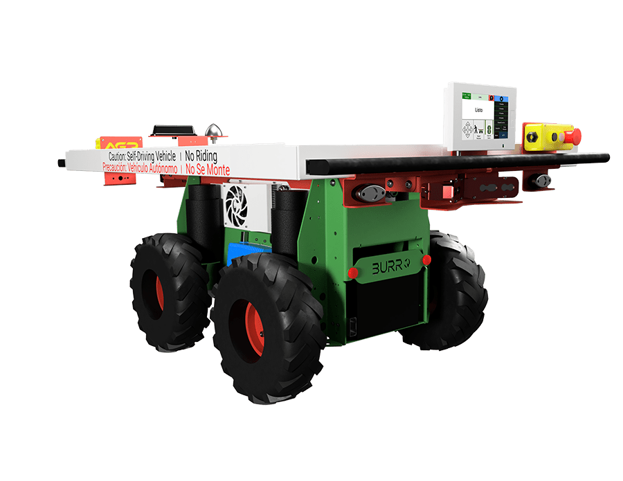
As an example company, I present Burro ( burro.ai ). Burro is a US company providing a robotic platform that works in high value row crops such as vineyards for grapes, blueberries, and plant nurseries. The company has been around for 4-5 years, and has recently raised about 25 million in Series B funding (these numbers are just estimates from memory). Burro operates in the US market, and perhaps South America. They have not entered the European market (so they are ripe for competitors here!!)
 
gen8_front_side_withUI_fixed-copy_smaller.png


Here are some of their training videos
 
 
Row Navigation - interesting User Interface, but basic capability
 
It seems that they have a good use case for transporting picked fruit from the pickers in the vineyard to the packing tables at the ends of the rows. It seems this would save time, and reduce the number of laborers required.
 
But here is a video (with very bad sound), that demonstrates the "scouting" use case. Here using software from a Computer Vision company, they are counting clusters of fruit. This is typically done to provide better estimates for harvest. This allows the vineyard manager to make proper arrangements for crates, workers, number of trucks, estimates on weight etc. This is a value add use case, and it looks like it would be an additional cost potentially.
 
"Scouting" with Bitwise (Computer Vision)
 
The Burro has the list price at the same cost as a Sub-Compact Tractor. ~15,000 - 25,000 USD. It also comes with a monthly "automation" fee of 200-300 USD. Over a four year period this could have a total value of about 100,000 USD. This probably does not include the software from the Computer Vision software. Which leads to may question.
 
What do you think?
  • Will it be the labor replacement?
  • or the making Ag more digital? Meaning that the value is best found in areas like Computer Vision, and sensors, and data collection.
  • Or Are we still missing the 'killer app' that will allow this robotic platform to take off?

Rethinking the Quadruped project

19 juin 2023 - 11:00

Hi all!


Inspired by the successful Quadruped builds at TRR, I'm eager to try another build. From the posts that have been made recently, I've learned about the importance of stronger servos, better batteries, and lighter weight. In my previous builds, I encountered issues with weak servos and excessive robot weight.

For my next project, I'm seeking advice on the servo/distribution/battery aspects. For an 8 or 12 DoF robot, I will need a lot of servos, and suitable battery. Hopefully, I could find the magical affordable servos with a torque of 40kg/cm and a speed of 0.1 s / 60°!

Regarding the electrical requirements, I need help calculating the required current flow and determining the appropriate battery capacity (C value). Should I assume that the stall current multiplied by the number of servos represents the maximum requirement? Or is there a larger requirement due to the combined impulse of all the servos?

I'm also rethinking power distribution. Would a custom board be necessary, considering the possibility of expanding the design to a 12DoF configuration?  This is obviously beyond the capabilities of a PCA9685.


Thanks!


IDE: Visual Studio Code + PlatformIO

04 octobre 2022 - 09:58

Hi all,


I am just now considering switching my IDE to Visual Studio Code and using PlatformIO.  I have seen on YouTube that it has many advantages. DroneBot Workshop and Andreas Spiess both have videos.  It is supposed to make working with Arduino and ESP32 boards easier, when you work with both.


What is your experiences and thoughts around this combination, are they good. Are you using it, or have any other recommendations?