


Documentation explaining how to assemble the Minus gripper

1 : Material
Servomotor 180° : 2
Minus mechanical gripper kit : 1
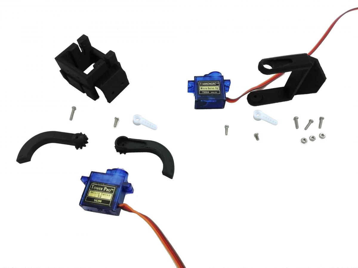
Content of the kit :
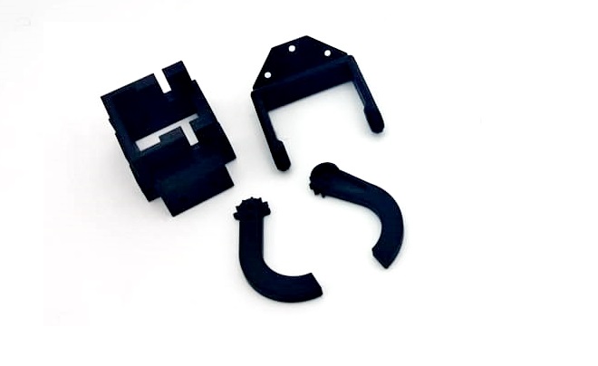
- 3D printed parts: 4
- M2 screws length 5 or 6mm : 1
- M2 screws length 8mm : 4
- M2 screws length 14mm : 5
- M2 nuts : 3
overview :
In order to ease the process you will need a raspberry pi + sd card installed connected on vigibot, with a standard configuration. Having a vigibot hat can also ease the servomotors connexion.
Optionnal :
Vigibot hat
2 : Assembly
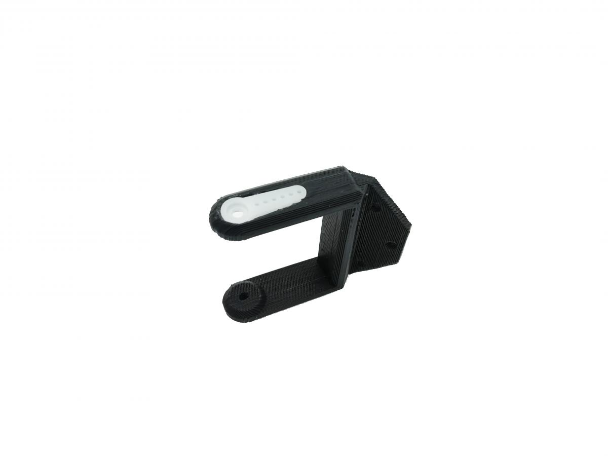
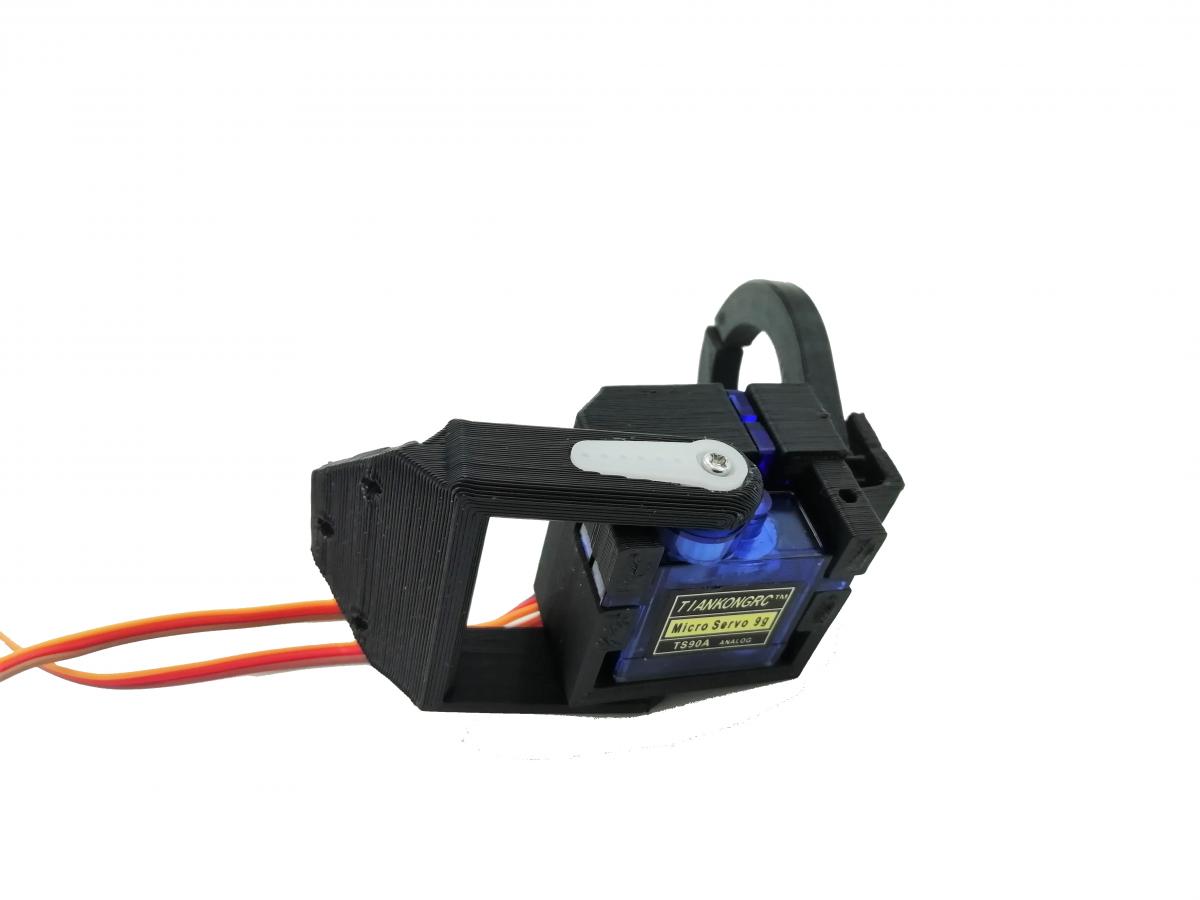
Insert the 2 plastic horns in the two 3D printed parts ( U part and finger ) and position them on the servomotors.
Connect the servomotor closing and opening the gripper on pin 7 of your raspberry pi configured by default.
Connect the servomotor lowering and raising the gripper on pin 8 of your raspberry pi configured by default.
Move the servomotors via vigibot and adjust the position of the horn on the servomotors shaft until it is as perfect as possible. (Any angular defect less than one notch of the servomotor shaft position can be corrected later on the site.)
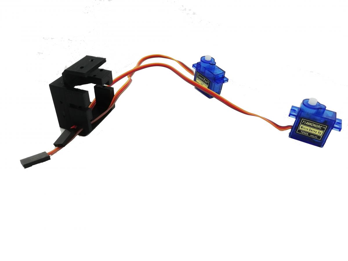
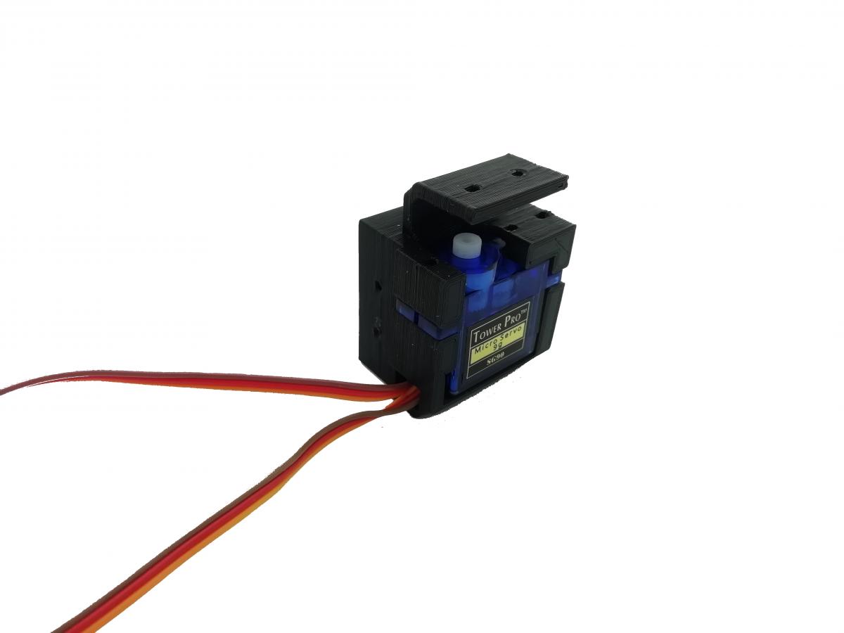
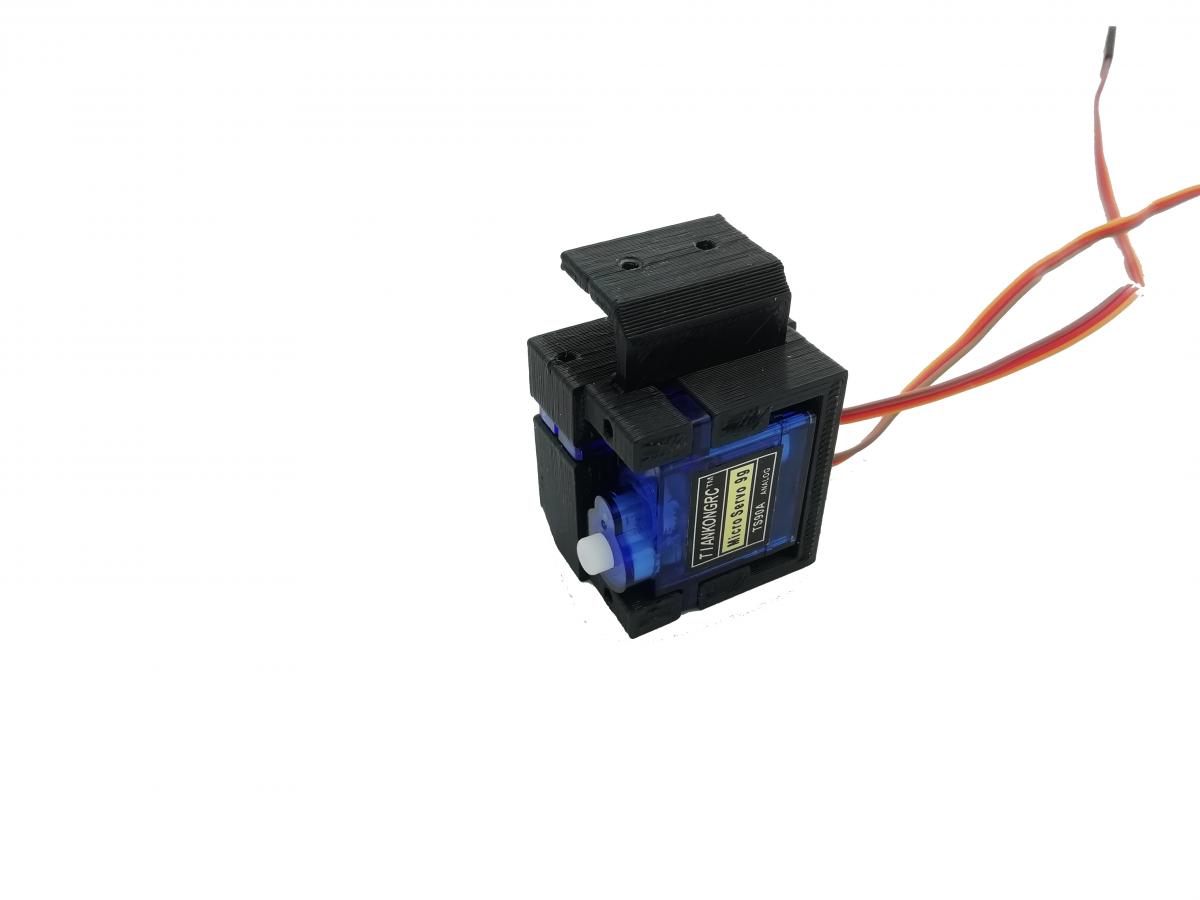
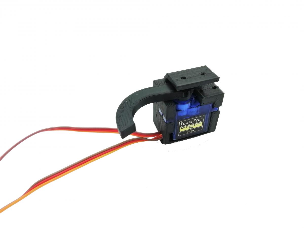
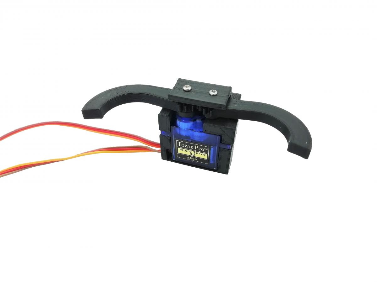
Once satisfied, insert the servomotors into the body of the griiper in the spaces provided for this purpose, having previously passed the cables of the servomotors through the holes and grooves that are provided for this purpose.
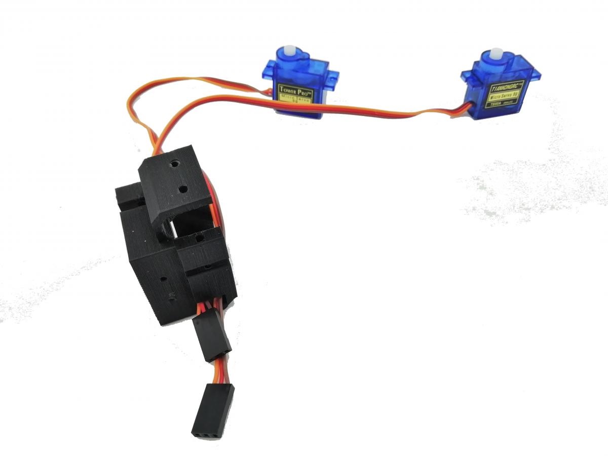
Note: for the servomotor allowing the upward movement of the gripper, the two positions are possible. Choose the one that best suits you based on whether you want it a bit lower or a little higher.
Don't hesitate to try both positions
Once the gripper is fully assembled, do not hesitate to check one last time that you are satisfied with the adjustment of the shaft according to the strokes of the servomotors by trying via vigibot.
Once the final check is complete,
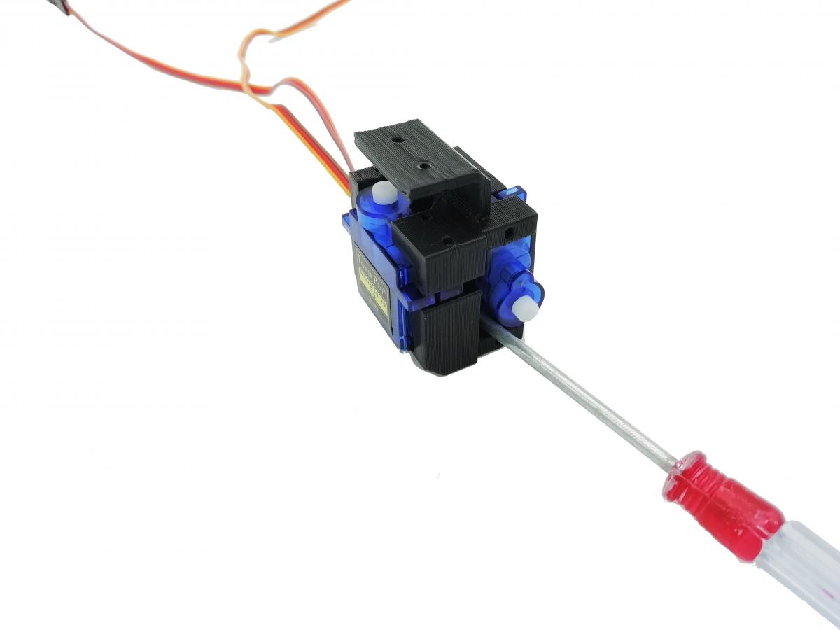
Attach the two servomotors to the gripper body with the 14mm screws.
Fix the servomotor horn of the U with the screw supplied with the servomotor provided for this purpose.
Fix the U counter axis with the 6mm screw.
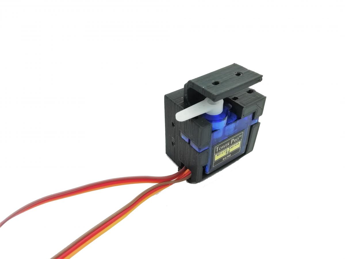
Use the 8mm screw to hold the gripper finger on the gripper opening and closing servomotor.
Insert the second finger of gripper symmetricaly with the first finger.
Secure this second finger with the last 14mm long screw.
You will have 3 screws length 8mm and 3 nuts remaining to fix the flat of the U on the chassis of your robot.
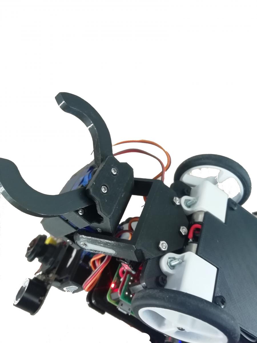
Some pictures:


![[Guide] How to use DECTalk, the Moonbase Alpha Voice, on your robot - dernier message par firened](https://www.robot-maker.com/forum/uploads/profile/photo-thumb-16821.jpg?_r=1639321316)
![[Mars Attacks!] Participating in the French Robot Cup 2024 ( Eurobot 2024) - dernier message par TNERA](https://www.robot-maker.com/forum/uploads/profile/photo-thumb-17784.png?_r=1662890323)


