Aller au contenu


Snyp54

Inscrit(e) (le) 03 nov. 2018
Déconnecté Dernière activité déc. 23 2021 03:02
-----

#111711 Comment configurer mon robot vigibot pour piloter Moteurs, Relais et Leds?

Posté par Snyp54 - 17 novembre 2020 - 09:41

Qu'est ce qu'un PCA9685  ? 

Un pca9685 est un composant assez répandu permettant de fournir 16 sorties PWM supplémentaire qui se branche en I2C ( GPIO 2 et 3  de votre raspberry pi = SDA et SCL ) . 


Comment configurer un PCA9685 sur Vigibot ?:


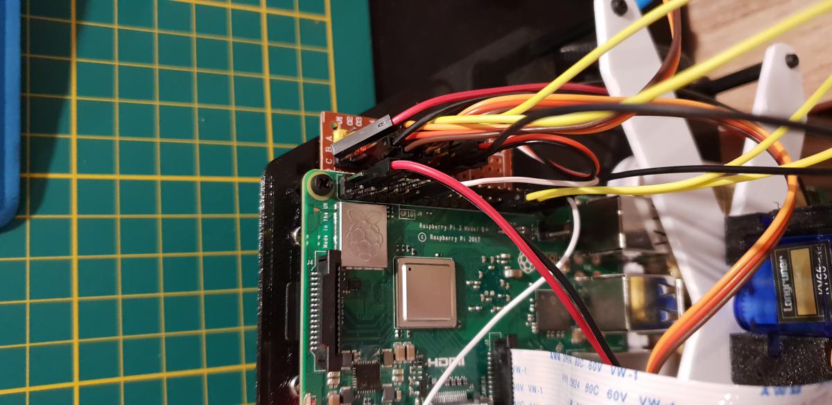
0) Branchez votre PCA à votre raspberry pi sur les broches I2C  2 et 3 ( SDA et SCL )


1) Connaître l'adresse I2C de votre pca9685 (en décimal) 


Méthode 1 :  lire la documentation de votre carte
Méthode 2 : lancer un scan I2C sur votre raspberry pi vous allez voir l'ensemble des périphérique I2C présent. ( recherchez " raspberry pi 
i2cdetect " )

=> Attention souvent les adresse I2C sont affichées en héxadécimal et pas en décimal ...
Dans ce cas il faudra conversion de l'adresse I2C hexadécimal en décimal )

Exemple pour un PCA9685 avec l'I2C par défaut à 0x70, la valeur décimal est 112.  

2) Ajouter l'adresse de Votre PCA dans votre configuration matérielle. 


Allez dans Configuration Matérielle, recherchez PCA9685ADDRESSESet ajoutez y votre adresse I2C (en décimal!) puis enregistrez votre configuration. 

=> Si vous avez rentré une adresse I2C valide, avec un pca branché votre robot robot devrait toujours fonctionné comme si rien n'avait changé. 
=> Si vous avez rentré une adresse I2C invalide, ou que votre PCA n'est plus branché, votre robot n'arrivera plus à se connecter et deviendra rouge sur vigibot. ( Supprimer l'adresse invalide ou la corriger avec l'adresse valide corrigera le problème . 


3) Configurer les sorties que vous souhaitez utiliser avec un PCA


Dans Configuration Matérielle, modifiez le OUTPUTS que vous souhaitez utiliser avec le PCA9685 et dans la case " adresse" remplacer le -1 par 0 pour l'attribuer au premier PCA9685 que dont vous avez enregistré l'adresse dans  PCA9685ADDRESSES.  

Dans GPIOS, vérifiez aussi que les numéro de sortie que vous désirez sont bien entre 0 et 15! 
Enregistrez votre configuration, si pas d'erreur de configuration normalement votre robot devrait fonctionner comme souhaité et la sortie de votre PCA être pilotée.

4) Bonus, brancher plusieurs PCA  : 

Ajoutez autant d'adresse  que de 
PCA9685 que vous avez dans le tableau PCA9685ADDRESSES.
Pour sélectionner le PCA dans OUTPUTS, changez le -1 dans adresse par  0 pour sélectionner votre premier pca, par 1 pour sélectionner le deuxième 1 etc...


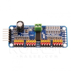
Exemple de carte avec PCA9685 :

https://www.robot-ma...rvomoteurs.html

driver-i2c-pour-16-servomoteurs.jpg


#110775 How to use stepper motor with Arduino & AccelStepper library

Posté par Snyp54 - 05 août 2020 - 02:22

Hi,

this is a code for use stepper motor on vigibot using an Arduino and AccelStepper library.

I use a A4988 stepper motor driver., two wire is needed between driver and Arduino ( Step & Dir).

/*
 * Vigibot Pi to Arduino Uart default remote configuration example by Mike118
 */

#include <AccelStepper.h>


// Meta Type : 

typedef struct {
 union {
  struct {
   int16_t x;
   int16_t y;
  };
  int16_t coordonnees[2];
  uint8_t bytes[4];
 };
} Point;

typedef struct {
 union {
  struct {
   int8_t x;
   int8_t y;
   int8_t z;
  };
  uint8_t bytes[3];
 };
} Vitesses;


// CONFIG 

#define PISERIAL Serial
#define NBPOSITIONS 2
#define FAILSAFE 250 // ms


// TTS 

#define TTSBUFFERSIZE 255  
uint8_t ttsBuffer[TTSBUFFERSIZE];
uint8_t ttsCurseur = 0;


// TX

#define TXFRAMESIZE (NBPOSITIONS * 4 + 17)

typedef struct {
 union {
  struct {
   uint8_t sync[4];               // 4
   Point positions[NBPOSITIONS];  // NBPOSITIONS * 4
   uint16_t val16[2];             // 2 * 2
   uint8_t choixCameras;          // 1
   Vitesses vitesses;             // 3
   uint8_t interrupteurs;         // 1
   uint8_t val8[4];               // 4
  };

  uint8_t bytes[TXFRAMESIZE];
 };
} TrameTx;


// RX

#define RXFRAMESIZE (NBPOSITIONS * 4 + 9)

typedef struct {
 union {
  struct {                       // Sizes
   uint8_t sync[4];              // 4
   Point positions[NBPOSITIONS]; // NBPOSITIONS * 4
   uint8_t choixCameras;         // 1
   Vitesses vitesses;            // 3
   uint8_t interrupteurs;        // 1
  };

  uint8_t bytes[RXFRAMESIZE];
 };
} TrameRx;


TrameTx trameTx;
TrameRx trameRx;

uint32_t lastTrameTimestamp = millis();

AccelStepper Xaxis(1, 2, 6);
AccelStepper Yaxis(1, 4, 7);

void setup() {
  PISERIAL.begin(115200);
  // add all your init here
  Xaxis.setMaxSpeed(400);
  Yaxis.setMaxSpeed(400);
  Xaxis.setSpeed(0);
  Yaxis.setSpeed(0);
}


void loop() {
  
  if(readPiSerial()) {
    // each time we receive a full trame run repeatedly:
    // use values inside trameRx to tell your robot how to move ...
    // trameRx.vitesses.x , trameRx.vitesses.y, trameRx.vitesses.z 
    // trameRx.positions[i].x trameRx.positions[i].y  etc.... 
    
    writePiSerial();
    lastTrameTimestamp = millis();
    updateSteppers();
  }

  if( millis() - lastTrameTimestamp > FAILSAFE ) {
    // Stop the robot in case the robot lost connection with the Pi
    stopSteppers();

  } else {
    // put your main code here, to run repeatedly:
    // avoid abstacle, run speed ...

    runSteppers();    
  }
}

bool readPiSerial() {
 uint8_t current;
 static uint8_t lastType = 0;
 static uint8_t n = 0;
 static uint8_t frame[RXFRAMESIZE];

 while(PISERIAL.available()) {
  current = PISERIAL.read();

  switch(n) {

   case 0:
    if(current == '$')
     n = 1;
    break;

   case 1:
    if(current != 'T' && lastType == 'T')
     writeTtsBuffer('\0');

    if(current == 'S' || current == 'T') {
     lastType = current;
     n = 2;
    } else
     n = 0;
    break;

    default:
    frame[n++] = current;

    if(n == RXFRAMESIZE) {

     if(lastType == 'T') {

      for(uint8_t i = 4; i < RXFRAMESIZE; i++) // Do not send the 4 sync data in tts
       writeTtsBuffer(frame[i]);

     } else if(lastType == 'S') {

      for(uint8_t p = 0; p < RXFRAMESIZE; p++)
       trameRx.bytes[p] = frame[p];

     }
     n = 0;
     return true;
    }

  }
 }

 return false;
}

void writePiSerial() {
 // Header, do not modify
 trameTx.sync[0] = '$';
 trameTx.sync[1] = 'R';
 trameTx.sync[2] = ' '; 
 trameTx.sync[3] = ' ';

 // modify the feedback according your need. By default we copy the trameRx content ... 
 for(uint8_t i = 0; i < NBPOSITIONS; i++) {
  trameTx.positions[i].x = trameRx.positions[i].x;
  trameTx.positions[i].y = trameRx.positions[i].y;
 }
 trameTx.val16[0] = 0;   // Voltage (will be updated by Raspberry pi)
 trameTx.val16[1] = 0;   // Percent (will be updated by Raspberry pi)
 trameTx.choixCameras = trameRx.choixCameras;
 trameTx.vitesses.x = trameRx.vitesses.x;
 trameTx.vitesses.y = trameRx.vitesses.y;
 trameTx.vitesses.z = trameRx.vitesses.z;
 trameTx.interrupteurs = trameRx.interrupteurs;
 trameTx.val8[0] = 0;   // CPU load (will be updated by Raspberry pi)
 trameTx.val8[1] = 0;   // Soc temp (will be updated by Raspberry pi)
 trameTx.val8[2] = 0;   // link (will be updated by Raspberry pi)
 trameTx.val8[3] = 0;   // RSSI (will be updated by Raspberry pi)

 for( uint8_t i = 0; i < TXFRAMESIZE; i++)
  PISERIAL.write(trameTx.bytes[i]);
}

void displayTtsBuffer (uint8_t * ttsBuffer, uint8_t bufferSize) {
  // you can modify this function to display text on a screen depending on your hardware...
  for( uint8_t i = 0; i < bufferSize; i++)
    Serial.write(ttsBuffer[i]);
  Serial.println("");
}

void writeTtsBuffer( uint8_t ttsChar) {
  static uint8_t ttsCurseur = 0;
  if( ttsCurseur < TTSBUFFERSIZE && ttsChar != '\0') {
    ttsBuffer[ttsCurseur] = ttsChar;
    ttsCurseur ++;
  }
  if( ttsCurseur == TTSBUFFERSIZE || ttsChar == '\0') {
    displayTtsBuffer (ttsBuffer, ttsCurseur);
    ttsCurseur = 0;
  }
}


void stopSteppers() {
  Xaxis.setSpeed(0);
  Yaxis.setSpeed(0);
  runSteppers();
}

void runSteppers() {
  Xaxis.runSpeed();
  Yaxis.runSpeed();
}


void updateSteppers() {
  Xaxis.setSpeed(trameTx.positions[0].x);
  Yaxis.setSpeed(trameTx.positions[0].y);
}


#108739 Précision moteur pas à pas en fraction de pas

Posté par Snyp54 - 06 avril 2020 - 09:20

Bonjour, pour le moteur, partir sur un motoreducteur avec un encodeur serait il envisageable?
Il faudrait juste faire une boucle pied pour l'asservissement de l'angle ?


#100423 Besoin d'aide avec python et arduino

Posté par Snyp54 - 28 novembre 2018 - 04:18

Bonjour a tous,

voila j'aurais besoin d'un coup de main. Je réalise une station météo avec un Arduino qui envoie ses données sur le port série @9600.

j'arrive à lire les valeurs sur le port série de l'Arduino IDE. Jusque la, pas de problème.


Maintenant j'utilise deux modules Dorji,un du coté de l'Arduino, un autre sur un serveur Debian avec adaptateur usb visible en /var/ttyUSB0 reglé en 9600 lié entre eux.

Coté arduino, la led rouge du module dorji s'allume lorsque le port série envoie quelque chose.

Coté serveur, la led bleu du module dorji s'allume signifiant qu'il à recu des données du module dorji de l'arduino

Mon problème est que je n'arrive pas ,du coté du serveur avec python, à lire le port /var/ttyUSB0.


Je vous met le code python(2.7) ainsi que le code Arduino.

#!/usr/bin/python
import serial 
import MySQLdb
import sys

#establish connection to MySQL.
dbConn = MySQLdb.connect("adress","login","pass","bdd_name") or die ("could not connect to database")
#open a cursor to the database
cursor = dbConn.cursor()

device = '/dev/ttyUSB0' # usually ttyUSB0 or ttyUSB1 for linux, or COM port number for windows
baudrate = 9600


def getSerialData():
 try:
  print "Trying...",device
  arduino = serial.Serial(device, baudrate) 
 except: 
  print "Failed to connect on",device    
 try:
     print "Trying to get data"
     next(arduino)
     data = arduino.readline()  #read the data from the arduino
     pieces = data.split("\t")  #split the data by the tab
     print "Data: %s" % data
     print "Piece 1: %s" % pieces[0]
     print "Piece 2: %s" % pieces[1]
     #Here we are going to insert the data into the Database
     try:
       print "Trying insertion..."
       cursor.execute("INSERT INTO data (temp,humidity) VALUES (%s,%s)", (pieces[0],pieces[1]))
       dbConn.commit() #commit the insert
       
     except MySQLdb.IntegrityError:
      print "failed to insert data"
     finally:
      print "closing cursor"
      
      del pieces[:]
 except:
  print "Failed to get data from Arduino!"
  sys.exit(1)


val = 0
while val == 0 :
 getSerialData()


#include <Wire.h>
#include "SparkFunHTU21D.h"

//Create an instance of the object
HTU21D myHumidity;

void setup()
{
  Serial.begin(9600);

  myHumidity.begin();
}

void loop()
{
  float humd = myHumidity.readHumidity();
  float temp = myHumidity.readTemperature();


  Serial.print(temp, 1); //HTU21D temperature (°C)
  Serial.print("\t"); 
  Serial.print(humd, 1); //HTU21D humidite (%)
  Serial.print("\t");

  delay(1000);
}

Merci pour l'aide que vous pourrez m'apporter.


#100233 Minus V1.0 Un vigibot simplifié pour Noël en précommande ?

Posté par Snyp54 - 17 novembre 2018 - 09:23

@Gamepigeek
La raspberry se met en veille,donc les ports gpio reste à l'état( a confirmer par mike118 ou pascal).

Voici donc mon bot fonctionnel.La powerbank doit être fixer ailleur pour l'équilibre du robot mais cela fonctionne en l'état. Je laisse comme ça en attendant le hat-ups.

Image(s) jointe(s)

  • 20181117_211311.jpg
  • 20181117_211331.jpg
  • 20181117_211340.jpg
  • 20181117_211346.jpg
  • 20181117_211352.jpg


#100053 Minus V1.0 Un vigibot simplifié pour Noël en précommande ?

Posté par Snyp54 - 11 novembre 2018 - 07:37

C'est bien une carte pour moteur cc.
Minus n'utilise pas de servo modifiés 360°.
Pour les caractéristique je laisse mike118.


#100041 Minus V1.0 Un vigibot simplifié pour Noël en précommande ?

Posté par Snyp54 - 11 novembre 2018 - 04:55

On est en train de rédiger le tuto avec la préparation de la raspberry, le câblage etc.


#99987 Minus V1.0 Un vigibot simplifié pour Noël en précommande ?

Posté par Snyp54 - 10 novembre 2018 - 09:01

Ça avance doucement mais sûrement 😁.
Ne faite pas attention filament, j'utilise du pteg.

Image(s) jointe(s)

  • 20181110_205919.jpg


#99874 Minus V1.0 Un vigibot simplifié pour Noël en précommande ?

Posté par Snyp54 - 06 novembre 2018 - 05:48

C'est pas pressé, mais c'est très bon projet.
Quoique

Image(s) jointe(s)

  • 20181106_184513.jpg